Code Flashed
CID - FMI
Part No.
Description
11
No ACTIVE Not applicable. Faults
12
No INACTIVE Not applicable. Faults
22
621 - 02
Downshift switch signal not correct.
190 - 08
Engine speed sensor signal not valid.
25
191 - 08
Transmission speed sensor signal not valid. Solenoid 1 open circuit. Solenoid 2 open circuit.
33
643 - 05
Solenoid 3 open circuit.
34
644 - 05
Solenoid 4 open circuit.
35
645 - 05
Solenoid 5 open circuit.
Normally Open
38 ± 3°C (100 ± 5°F)
26.7°C MIN (80°F MIN)
Normally Closed
Primary Steering Pressure(EMS)
1200 kPa MAX (175 psi MAX)
700 ± 100 kPa (100 ± 15 psi)
A-C, Normally Closed A-B, Normally Open
Engine Coolant Temperature(EMS)
107.0 ± 3.0°C (224.6 ± 6.0°F)
93.0°C MIN (199.0°F MIN)
Normally Closed
Torque Converter Oil Temperature (EMS)
129.0 ± 3.0°C (264.0 ± 6.0°F)
118.0°C MIN (244.0°F MIN)
Normally Closed
Fuel Pressure (EMS)
70 kPa MAX (10 psi MAX)
40 ± 20 kPa (6.0 ± 3.0 psi)
Normally Closed
Engine Oil Pressure (EMS)
90± 21 kPa (13 ± 3.0 psi)
70± 21 kPa (10 ± 3.0 psi)
A-B, Normally Open A-C, Normally Closed
Brake Oil Pressure (EMS)
10700 kPa MAX (1550 psi MAX)
8960 ± 345 kPa (1300 ± 50 psi)
A-B, Normally Open A-C, Normally Closed
9W-0549
Refrigerant Pressure (A/C)
213 kPa MAX (31 psi MAX)
172 kPa MIN (25 psi MIN)
Normally Open
114-5333
Refrigerant Pressure (A/C)
275 to 1750 kPa ¹ (40 to 255 psi)
— —
Normally Open ²
3E-6453
3E-6455 3E-7693
646 - 05
Solenoid 6 open circuit.
41
641 - 06
Solenoid 1 short to ground.
42
642 - 06
Solenoid 2 short to ground.
43
643 - 06
Solenoid 3 short to ground.
44
644 - 06
Solenoid 4 short to ground.
Function Supplemental Steering Oil Flow Engine Coolant Temperature (Start Aid)
Machine Location
Connector
C 40 CONTACTS
25 CONTACTS
645 - 06
Solenoid 5 short to ground.
646 - 06
Solenoid 6 short to ground.
51
641 - 03
Solenoid 1 short to +battery.
52
642 - 03
Solenoid 2 short to +battery.
53
643 - 03
Solenoid 3 short to +battery.
54
644 - 03
Solenoid 4 short to +battery.
55
645 - 03
Solenoid 5 short to +battery.
646 - 03
Solenoid 6 short to +battery.
660 - 02
Invalid shift lever input line 12.
3
662 - 02
Invalid shift lever input line 14.
64
663 - 02
Invalid shift lever input line 15.
65
664 - 02
Invalid shift lever input line 16.
66
665 - 02
Invalid shift lever input line 17.
67
666 - 02
Invalid shift lever input line 18.
68
667 - 02
Invalid shift lever input line 19.
69
668 - 02
Invalid shift lever input.
71
168 - 00
System voltage above normal.
72
168 - 01
System voltage below normal.
74
650 - 02
Invalid harness code.
15 17
1
2 22
8
E - 113-5803 G - 8Y-7607
A-13
2
A - 4E-5045 B - 8R-2919 Standard
1
A - 4E-5045 L - 4E-0598
B-7
2
A - 4E-5045 B - 8R-4671 Attachment
1
A - 4E-5045 P - 102-5889
B-5
2
A - 4E-5045 GGG - 4E-8960
A-3
1
D - 8R-3667 P - 102-5889 Standard
B-9
C
P - 102-5889 Transmission Shifter
D-5
1
D - 8R-3667 FF - 4E-0599 Attachment
B-9,C-10
5
FF - 4E-0599 Attachment GG - 8Y-8479 Attachment
E-10
1
P - 102-5889 FF - 4E-0599 Attachment
B-9,C-9
A
LL - 101-5308 Attachment Intermittent Wiper Switch
D-6
*
F - 102-5888 Operator Monitor (EMS)
E-3
A
P - 102-5889 SS - 7X-6015
C-4
2
A - 4E-5045 B - 8R-2919 Standard
B-3
6
A - 4E-5045 D - 8R-3667
B-9
2
A - 4E-5045 B - 8R-4671 Attachment
7
A - 4E-5045 Positioner Solenoids
B-6
D-13
*
B - 8R-4671 Attachment LH Head/Turn/Marker Lamp
F-1
D-13, E-14
*
B - 8R-4671 Attachment RH Head/Turn/Marker Lamp
E-1
A
L - 4E-0598 UU - 101-9161 Standard
D-9
A
L - 4E-0598 Timer (AIH) Attachment
D-9
20 CONTACTS
26
6 CONTACTS
A - 4E-5045 C - 8R-3305 Standard
3
A - 4E-5045 C - 8R-3922 Attachment
4
A - 4E-5045 E - 113-5803
C-11
4
A - 4E-5045 E - 113-5803
C-12 4 CONTACTS
E-10
A-3
A-3,D-2
1
L - 4E-0598 N - 102-5891 Standard
D-9
8
N - 102-5891 Rear Wiper Motor
E-9
1
L - 4E-0598 N - 4E-4186 Attachment
D-9, F-7
C
P - 102-5889 Front Wiper Motor
C-4
C 13
1
L - 4E-0598 P - 102-5889
C-6
1
L - 4E-0598 P - 102-5889
C-6
C
P - 102-5889 Transmission Shifter
D-6
10 CONTACTS
28
24 29
7
33
6
16
A
7
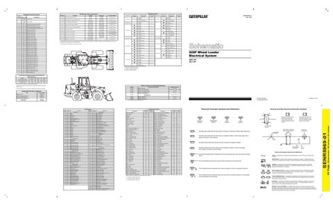
928F Wheel Loader Electrical System 8AK1-UP 2XL1-UP
11
1
10
3
7 CONTACTS
B-3, E-2
3
5
21 6
B
8 CONTACTS
SENR5969-01 May 1994
E-3
B
2
5
37
34
32
14 4 4 20
9 CONTACTS
9
19
23
*
F - 102-5888 Cluster Gauge
Schematic Location
FF - 4E-0599 Attachment Data Link Plug Attachment
30
18
Invalid shift lever input line 13.
63
27
31
8 35
F-5
Harness And/Or Components
5
12
61
F - 102-5888 P - 102-5889
Machine Location
Connector
E-10
12 CONTACTS
56
Schematic Location
FF - 4E-0599 Attachment Transmission Control Attachment
² Contact position at the contacts of the harness connector.
46
Harness And/Or Components
*
24 CONTACTS
¹ A hysteresis band exists: with increasing pressure the closed condition can be maintained up to 2800 kPa (405 psi), with decreasing pressure the closed condition can be maintained down to 170 kPa (25 psi).
45
661 - 02
1.5 grams (.05 oz)
3E-6454
36
62
4 grams (.14 oz)
3E-6451
24
642 - 05
Contact Position
3E-6450
Auto/manual switch signal not correct.
641 - 05
Deactuate
3E-6449
368 - 02
32
Actuate
3E-6429
21
31
Connector Location
Off Machine Switch Specification
Diagnostic Code Conversion
Machine locations are repeated for connectors located close together. *= Connector is located at the component. A = Connector is located in right console area. B = Connector is located at breaker box. C = Connector is located in dash area.
ACTIVATION OF DIAGNOSTIC INDICATOR OPERATIONS (Quick Reference) 16
Contact 5¹
To Scroll ACTIVE Faults
Ground ²
Open
Open
To Scroll INACTIVE Faults
Open
Open
Ground ²
To Clear ³ Faults
Open
Ground
Open
¹ These contacts are located in the harness code connector.
34
14
² Remove the connection to ground to place the desired information shown during scrolling on-hold.
1
33
8 26 2
C
9 29
A
10 1
4
8
11
6
20
Related Electrical Service Manuals Title Alternator; K1/N1
SENR3685
Electronic Transmission Control
SENR5751
Electronic Monitoring System Starting Motor; Consist 9X-99953 E-2298 (41MT) 8C-4773(JE)
SENR2945
3
27
35
37
Form Number
12
6
B 19
7
17 3 15
21
Part No. 28
31 23
Resistor, Sender and Solenoid Specifications
13
4
18 5
22
³ A fault is cleared onlr while it is on-hold. A fault that is active cannot be cleared.
5
30
2
Resistor - Alternator
9G-1950
Resistor - Blower Motor Speed
24
Resistance (Ohms)¹ 39 ± 1.95 Overall 2.0 ± .1; Tap 1.0 ± .05
8T-8813
Solenoid - Air Conditioner Clutch
14.4 ± 0.6
102-0347
Solenoid - Air Conditioner Clutch
14.4 ± 0.6
8C-3663
Solenoid - Engine Shutdown Start (Latch) Coil Stop (Unlatch) Coil
7
32
Component Description
6T-7864
1.55 ± 0.1510.3 ± 1.03
Solenoid - Ride Control 9X-3267 Solenoid - Start Aid 3E-6332 Solenoids - Transmission 3E-6269 ¹ At room temperature unless otherwise noted.
SENR3581 SENR3859
Wire Color
Wire Number
Wire Color
Electrical Schematic Symbols And Definitions
101
RD
BAT
500
BR
WIPER - FRONT (PARK)
Alarm - Action (EMS)
Schematic Location D-3
102
BU
HDLMP
501
GN
WIPER - FRONT (LO)
Alarm - Backup
D-14, E-15
1
Sensor - Engine Speed (Trans)
B-10
104
YL
AUX CKT
502
OR
WIPER - FRONT (HI)
2
21
KEY START SW
503
BR
Sensor - Trans Speed (Speedometer)
F-11
BR
Alternator
F-14
105
WIPER - REAR (PARK)
108
BU
AUX CKT
504
YL
WIPER - REAR (LO)
Batteries
B-15, F-14
3
Shifter - Transmission
F-5
34
109
OR
ALT OUTPUT (+) TERM
505
BU
WIPER - REAR (HI)
Breaker - Blower Motor
C-9
A
Solenoid - Air Conditioner Clutch
C-14, D-15
22
112
PU
MAIN POWER RELAY OUTPUT
506
PU
WASHER - FRONT
Breaker - Main
A-14
B
Solenoid - Bucket Float
B-6
A
113
OR
OPR MON PANEL
507
WH
WASHER - REAR
114
GN
WARNING HORN (FORWARD)
508
PU
RADIO SPEAKER - LEFT
Breaker - Running Lamp
A-13
B
Solenoid - Bucket Positioner
B-6
A
116
BR
AUX CKT
509
WH
RADIO SPEAKER - LEFT (COMMON)
Control - Autoshift
E-10
4
Solenoid — Engine Shutdown
C-14
23
118
GY
AUX CKT
511
BR
RADIO SPEAKER - RIGHT
Converters - Voltage
F-6
5
Solenoid - Lift Positioner
B-6
A
120
YL
AUX CKT
512
GN
RADIO SPEAKER - RIGHT (COMMON)
Flasher
E-4
C
Solenoid — Ride Control
B-2, E-1
24
C-9
A
Solenoid - Start Aid
C-14
26 19
Description
Description
Component
Accessory Circuits
Power Circuits
121
YL
BACKUP ALARM TO LAMP
513
OR
A/C COMPRESSOR/REFRIGERANT PRESS SW
124
GN
A/C
515
GY
BLOWER MOTOR (HI)
Fuses
126
PK
XMSN CONT
516
GN
BLOWER MOTOR (MEDIUM)
Fuses - Alarm, Horn, Stoplamp, Key
127
OR
AUX CKT
517
BU
BLOWER MOTOR (LO)
Machine Location C
Component Sender - Torque Converter Temp (Gauge)
Machine Location 19 20
A-13
B
Solenoids - Transmission
F-9
F-3
C
Switch - Beacon
E-7
A
D-4
C
PK
AUX CKT
521
YL
129
BU
AUX CKT
522
WH
A/C CLUTCH TO THERMOSTAT SW
Gauge - Fuel Level
E-3
C
Switch - Blower
130
GN
AUX CKT
537
GN
TURN SIGNAL SW TO FLASHER
Gauge - Hydraulic Oil Temp
E-3
C
Switch - Brake Oil Press (EMS)
135
BU
AUX CKT
538
BR
HAZARD INDICATOR
144
GN
AUX CKT
Gauge - Torque Converter Temp
F-3
C
Switch - Bucket Positioner
160
PU
AUX CKT
603
PK
ROTARY BEACON
Ground - Platform
C-5
6
164
WH
XMSN CONT TO DATA LINK
604
OR
STOP LAMP
Ground - Engine End Frame
A-6
7
193
PU
AUX CKT
605
YL
TURN LAMP - LEFT
606
GY
TURN LAMP - RIGHT
Lighting Circuits
Schematic Location B-13
Gauge - Engine Coolant Temp
128
A/C SW TO REFRIGERANT SW
F-8
27
C-2, F-1
28
Switch - Disconnect
B-15
37
Switch - Engine Coolant Temp (EMS)
F-12
2
Ground - Engine End Frame
B-5
35
Switch - Engine Coolant Temp (Start Aid)
F-12
2
200
BK
MAIN CHASSIS
608
GN
FLOOD LAMP - REAR
Ground - Roof
E-6
5
Switch - Engine Oil Press (EMS)
B-14
23
201
BK
OPR MON PANEL
610
OR
HEAD LAMP BASIC
Heater - Air Intake
202
BK
XMSN CONT
611
PU
HEAD LAMP HI
206
BK
BAT SIDE OF DISCONNECT
614
PU
PARK/TAIL/DASH LAMP
276
BK
XMSN CONT IDENT CODE 0
615
YL
CAB FLOOD LAMP/ROPS
277
BK
617
BR
278
BK
XMSN CONT IDENT CODE 2
619
GN
279
BK
XMSN CONT IDENT CODE 3
280
BK
XMSN CONT IDENT CODE 4
710
281
BK
XMSN CONT IDENT CODE 5 Basic Machine Circuits
Ground Circuits
XMSN CONT IDENT CODE 1
D-11
8
Switch - Flood Lamp
D-7
A
C-2, E-1
9
Switch - Forward Horn
D-5
34
Lamp - Action (EMS)
D-3
C
Switch - Front Intermittent Wiper/Washer
E-6
A
TAIL/POSITION LAMP - LEFT (ROAD PKG)/WIDTH
Lamp - Air Intake Heater
F-3
C
Switch - Front Wiper/Washer
D-8
A
HEAD LAMP LO
Lamp - Diagnostic (Trans)
E-10
10
Switch - Fuel Press (EMS)
B-14
23
F-3
C
Switch - Key Start
D-6
A
C-2, F-1
29
Control Circuits
Horn - Forward
Lamp - Neutralizer Override
GN
XMSN SPEED PICKUP SIGNAL
720
PU
XMSN BRAKE SW
Lamp - Ride Control
F-3
C
Switch - Lift Positioner
751
GN
XMSN SHIFT SOL NO. 1 OR 3
Meter - Service
E-7
A
Switch - Neutralizer
A-3
30
YL
XMSN SHIFT SOL NO. 2
Meter - Speedometer
F-4
C
Switch - Parking Brake (EMS)
D-10
31
Monitor - Operator (EMS)
E-3
C
Switch - Primary Steering Press (EMS)
A-15
32
D-8
A
D-15, E-12
17
301
BU
STARTER NO. 1 SOL
752
304
WH
STARTER RELAY NO. 1 OUTPUT
754
BU
XMSN SHIFT SOL NO. 3 OR 1
306
GN
STARTER RELAY COIL TO XMSN SHIFTER
755
OR
XMSN SHIFT SOL NO. 4 OR 5
307
OR
KEY START SW TO XMSN SHIFTER
761
GY
LIFT KICKOUT SOL SW
Motor - Blower
C-3
11
Switch - Rear Wiper/Washer
308
YL
MAIN POWER RELAY COIL
762
YL
BUCKET POSITIONER SOL SW
Motor - Front Washer
F-8
12
Switch - Refrigerant Press (AC)
309
GY
ALTERNATOR REGULATOR TERM
900
PU
XMSN SHIFT SOL NO. 5 OR 4
310
PU
START AID SW TO START AID SOL
901
WH
XMSN SHIFT SOL NO. 6
311
WH
START AID SOL TO TEMP SW
910
YL
321
BR
BCKP ALARM LAMP TRAVEL ALARM
921
WH
322
GY
WARNING HORN (FORWARD)
922
BR
XMSN SOL NO 2 RETURN
326
PU
KEY START SW “C” TERM
923
GY
XMSN SOL NO 3 OR 1 RETURN
373
GN
AIH TIMER
924
GN
XMSN SOL NO 4 OR 5 RETURN
925
YL
XMSN SOL NO 5 OR 4 RETURN
403
GN
ALTERNATOR (R) TERM
926
BU
XMSN SOL NO 6 RETURN
405
GY
OPR MON OIL PRESS (LO SETTlNG)
944
OR
CAT DATA LINK +
506
PU
OPR MON COOLANT TEMP
945
BR
409
OR
OPR MON NEUT
963
410
WH
OPR MON ACTION ALARM
964
411
PK
OPR MON ACTION LAMP
413
BR
OPR MON FUEL PRESS
Monitoring Circuits
Motor - Front Wiper
B-4
13
Switch - Ride Control
E-7
A
XMSN NEUTIZER OVERRIDE INDICATOR
Motor - Rear Washer
F-8
12
Switch - Running Lamp
D-7
A
XMSN SOL NO 1 OR 3 RETURN
Motor - Rear Wiper
E-9
14
Switch - Start Aid
E-9
A
Motor - Starting
F-13
15
Switch - Stop Lamp
Radio
F-7
16
Switch - Supplemental Oil Flow (EMS)
Relay - Air Intake Heater
D-11
15
Switch - Test (EMS)
E-8
A
Relay - Main
A-13
B
Switch - Thermostat
C-3
C
CAT DATALINK
Relay - Start
A-14
B
Switch - Torque Converter Oil Temp (EMS)
B-13
19
GN
BUCKET/FORK POSITION DETENT COIL
Resistor - Alternator
BU
FORK POSITION SELECT
965
WH
TRANS SOL 1 SW TO GND
966
GY
A-3
30
A-15
32
A-13
B
Switch - Transmission Auto/Manual
E-8
A
Resistor - Blower Motor Speed
C-3
11
Switch - Transmission Downshift
B-6
33
TRANS SOL 3 SW TO GND
Sender - Engine Coolant Temp (Gauge)
F-12
2
Switch - Transmission Neutralizer Override
E-8
A
415
GN
OPR MON TEST SW
967
BU
TRANS SOL 1 & SOL 3 SW TO B+ (CST ONLY)
Sender - Fuel Level (Gauge)
E-12
17
Switch - Turn Signal
F-5
34
416
OR
SUPPL STER SW
968
BR
TRANS SOL 2 SW TO GND
B-13
18
A
GY
PRIMARY STER SW
969
YL
Timer - Air Intake Heater
D-9
417
Sender - Hydraulic Oil Temp (Gauge)
TRANS SOL 3 SW TO B+
419
YL
OPR MON PARKING BRAKE
970
GN
TRANS SOL 4 SW TO GND
Machine locations are repeated for components located close together.
428
OR
OPR MON XMSN OIL TEMP
971
YL
TRANS SOL 5 SW TO GND
A = Components located at right console.
432
PK
OPR MON BRAKE PRESS (OIL)
972
BU
TRANS SOL 6SW TO GND
B = Components located at breaker box.
441
OR
ENG COOLANT TEMP GAGE
973
BR
XMSN CONTROL - AUTO/MANUAL SW 2
442
GY
HYD SYSTEM TEMP GAGE
974
PU
XMSN CONTROL - SLOW MODE SW
443
YL
POWER TRAIN TEMP GAGE
975
WH
XMSN CONTROL - SOL RETURN
447
PK
FUEL LEVEL GAGE
976
OR
RIDE CONT SOL
449
BU
SPDOM SENDER (SIGNAL NO. 1)
977
YL
XMSN CONTROL - AUTO/MANUAL SW 1
450
YL
TACH SENDER (+)
978
GN
XMSN CONTROL - SLOW MODE SW 1
987
WH
DIVERTER SOL
8757
WH
XMSN CONTROL
B758
GN
XMSN CONTROL
B766
WH
KICKOUTS/DETENT DISABLE SW TO KICKOUTS
C920
GY
XMSN CONTROL - DIAGNOSTIC LAMP
Printed in U.S.A.
© 1994 Caterpillar All Rights Reserved
Component Location
Wire Description Wire Number
17.8 ± 0.9 6.0 33.8 ± 1.0
Harness And Wire Electrical Schematic Symbols A
AA
T
Pressure Symbol
Temperature Symbol
Level Symbol
Typical representation of a Deutsch connector. The plug contains all sockets and the receptacle contains all pins.
Receptacle
Plug
Flow Symbol
1 2
1 2
1
2
Typical representation of a Sure-Seal connector. The plug and receptacle contain both pins and sockets.
Pin or Socket Number Wire, Cable, or Harness Assembly Identification
Normally open switch that will close with an increase of a specific condition (temp-press-etc.).
Component Part Number
Single Wire Connector C
Normally open switch that is closed due to an applied condition, and will open again with a specific decrease in that condition.
A
A 325-PK-14
Pin
AA 1
9X-1123 325-PK-14
Wire Color
Socket
Normally closed switch that will open with an increase of a specific condition. 2
200-BK-14
Circuit Number Identification
Normally closed switch that is open due to an applied condition, and will close again with a specific decrease in that condition.
Wire Gauge
Electrical Schematic Symbols And Definitions
The circle indicates that the component has screw terminals and a wire can be disconnected from it.
FUSE - A component in an electrical circuit that will open the circuit if too much current flows through it. REED SWITCH - A switch whose contacts are controlled by a magnet. A magnet closes the contacts of a normally open reed switch; it opens the contacts of a normally closed reed switch.
No circle indicates that the wire cannot be disconnected from the component.
T
SENDER - A component that is used with a temperature or pressure gauge. The sender measures the temperature or pressure. Its resistance changes to give an indication to the gauge of the temperature or pressure.
This indicates that the component has a wire connected to it that is connected to ground. RELAY (Magnetic Switch) - A relay is an electrical component that is activated by electricity. It has a coil that makes an electromagnet when current flows through it. The electromagnet can open or close the switch part of the relay.
This indicates that the component does not have a wire connected to ground. It is grounded by being fastened to the machine.
CIRCUIT BREAKER (C/B) - A component in an electrical circuit that will open the circuit if too much current flows through it. This does not destroy the circuit breaker and it can be reset to become part of the circuit again.
C = Components located in dash area.
SOLENOID - A solenoid is an electrical component that is activated by electricity. It has a coil that makes an electromagnet when current flows through it. The electromagnet can open or close a valve or move a piece of metal that can do work. MAGNETIC LATCH SOLENOID - A magnetic latch solenoid is an electrical component that is activated by electricity and held latch by a permanent magnet. It has two coils (latch and unlatch) that make electromagnet when current flows through them. It also has an internal switch that places the latch coil circuit open at the time the coil latches.
(Dimensions: 39 inches x 24 inches)
Contact 3¹
20 Page,
Contact 1¹
SENR5969-01
Operation