Wire Description Wire Number
Wire Color
101
RD
Battery +
102
RD
Marker Lamps
539
BU
Right Turn Indicator
105
RD
Kay Switch
540
WH
Left Turn Indicator
538
BR
Power Circuits
Diagnostic Code Conversion Code Flashed 11
CID - FMI
Description
No Active Faults No Inactive Faults
Not Applicable
Accesory Circuits (Continued)
108
RD
Converter Output
567
WH
Blower To A/C Sw
109
RD
Alt B+
571
OR
Ride Control Signal
110
GN
Flasher
112
PU
Main Breaker Output
603
PK
114
RD
Fwd Horn
604
OR
Stop Lamp
115
RD
Aux Circuit Breaker
605
YL
Left Turn
117
RD
Main Breaker
606
GY
Right Turn
GY
Wipers
608
GN
Rear Flood Lamps
YL
Sw'd Converter
610
OR
Dimmer Switch
14
Not Applicable
122
RD
Misc
611
PU
High Beam Headlights
15
Standard Speed XMSN
123
WH
Gauges and Indicator Light
614
PU
Marker Lights
Not Applicable
124
GN
Blower
615
YL
Cab Flood Lights
17
Not Applicable
126
PK
XMSN Control
619
GN
Low Beam Headlights
18
Low Speed XMSN
127
OR
Flood Lights
633
BU
COSA Turn Signal
Not Applicable
128
PK
Kickout & Ride Control
665
BR
Corner Markers
691
GY
COSA Flasher
31
641 - 05
Forward High Solenoid Open Circuit
129
BU
Cigar Lighter
32
642 - 05
Reverse Solenoid Open Circuit
130
RD
Stop Lamps
33
643 - 05
Forward Low Solenoid Open Circuit
133
OR
FNR
702
OR
XMSN Neutralizer
34
644 - 05
Speed 1 Solenoid Open Circuit
135
BU
Sw'd Converter Output
710
GN
XMSN Speed
35
645 - 05
Speed 2 Solenoid Open Circuit
136
GN
Secondary Steering
720
PU
Neutralizer 1
36
646 - 05
Speed 3 Solenoid Open Circuit
140
BU
Rear Window Defroster
727
GN
Secondary Steering Output
37
346 - 05
Ride Control Relay Open Circuit
144
GN
Beacon & Heated Seat
751
GN
XMSN Solenoid 1
38
683 - 05
Parking Brake Alarming Open Circuit
158
BR
Condenser Motors
752
YL
XMSN Solenoid 2
39
421 - 05
Load Check Relay Open Circuit
161
PK
Ride Control
754
BU
XMSN Solenoid 3
41
641 - 06
Forward High Solenoid Short to Ground
188
WH
Start Aid
755
OR
XMSN Solenoid 4
42
642 - 06
Reverse Solenoid Short to Ground
761
GY
Lift Position
43
643 - 06
Forward Low Solenoid Short to Ground
200
BK
Main Chassis
762
YL
Bucket Positioner
44
644 - 06
Speed 1 Solenoid Short to Ground
202
BK
Controller
779
WH
Quick Coupler Engaged
45
645 - 06
Speed 2 Solenoid Short to Ground
276
BK
XMSN Ident Code 0
780
PU
Quick Coupler Disengaged
46
646 - 06
Speed 3 Solenoid Short to Ground
277
BK
XMSN Ident Code 1
900
PU
XMSN Solenoid 5
47
346 - 06
Ride Control Relay Short to Ground
278
BK
XMSN Ident Code 2
901
WH
XMSN Solenoid 6
48
683 - 06
Parking Brake Alarming Short to Ground
279
BK
XMSN Ident Code 3
944
OR
CAT Data Link +
49
421 - 06
Load Check Relay Short to Ground
945
BR
CAT Data Link -
51
641 - 03
Forward High Solenoid Short to Ground
301
BU
Fuel On
963
GN
Tilt Positioner
52
642 - 03
Reverse Solenoid Short to Battery
304
WH
Start Relay Output
964
BU
Fork Positioner
53
643 - 03
Forward Low Solenoid Short to Battery
306
GN
Start Disable Output
973
BR
Auto/Manuel XMSN
54
644 - 03
Speed 1 Solenoid Short to Battery
307
OR
Key Switch Start
975
WH
Solenoid Return
55
645 - 03
Speed 2 Solenoid Short to Battery
308
YL
Key Switch Run
976
OR
Ride Control Output
Basic Machine Circuits
56
646 - 03
Speed 3 Solenoid Short to Battery
310
PU
Start Aid Signal
978
GN
Downshift Signal
57
346 - 03
Ride Control Relay Short to Battery
321
BR
Backup Alarm
A221
BK
XMSN Option Code 0
58
683 - 03
Parking Brake Alarm Short to Battery
322
GY
Fwd Horn
A222
BK
XMSN Option Code 1
59
421 - 03
Load Check Relay Short to Battery
326
PU
Key Switch Off
A514
YL
Parking Brake Alarm
61
190 - 08
Engine Speed Sensor
331
OR
XMSN Backup Alarm Output
A519
GN
V-Link Ride Control Output
62
191 - 08
Transmission Speed Sensor
373
GN
Start Aid Signal
A520
BU
V-Link Ride Control Signal
63
668 - 02
Invalid Shift Lever input
A538
OR
Rear Window Defroster Signal
64
168 - 00
Battery Voltage Above Normal
403
A541
PU
COSA Turn Indicator
Monitoring Circuits GN
Alternator (R) Treminal
65
168 - 01
Battery Voltage Below Normal
404
YL
XMSN Oil Temperature Indicator
A576
GN
Air Seat
66
650 - 02
Invalid Harness Code Input
405
GY
Engine Oil Temperature Indicator
C444
YL
Alternator Field Excitation Coil
67
687 - 02
Invalid Option Code Input
406
PU
Coolant Temperature Indicator
C446
PK
Filter Warning
68
367 - 02
Invalid Ride Control Switch Input
417
GY
Steering Pressure
C470
BR
Alarm Signal
69
621 - 02
Invalid Downshift Switch
419
YL
Park Brake Indicator
C471
GN
Alternator Warning
441
OR
Coolant Temperature
C904
GN
FNR Solenoid 1
442
GY
Hydraulic Temperature
C920
GY
Diagnostic Indicator
443
YL
Torque Converter Temperature
E417
OR
Parking Brake Signal
447
PK
Fuel Level
E419
BU
Seat Alarm
449
BU
Ground Speed
E701
PK
Ride Control On
450
YL
Engine Speed
E800
GN
Seat Alarm Output
453
PK
Secondary Steering Indicator
F748
WH
Ride Control
483
BR
Oil Pressure Indicator
F765
BR
Parking Brake
484
YL
Primary Steering Indicator
F766
WH
Detent Override
F853
BR
TUV Speed Limiter
500
BR
Wiper - Front (Park)
F880
BR
FNR Solenoid 2
501
GN
Wiper - Front (Low)
G728
YL
Kickouts On/Off
502
OR
Wiper - Front (High)
G742
GN
Key Switch Run Signal
503
BR
Wiper - Rear (Park)
G750
GU
XMSN Fwd
504
YL
Wiper - Rear (Low)
G755
GY
XMSN Rev
505
BU
Wiper - Rear (High)
G757
OR
XMSN Neutralizer 2
506
PU
Waher - Front
G760
WH
XMSN Speed 2
507
WH
Washer - Rear
G761
YL
XMSN Speed 3
508
PU
Radio Speaker - Left
G762
BR
XMSN Speed 4
Accesory Circuits
509
WH
Radio Speaker - Left (Common)
G763
PU
FNR Switch 1
Component identifiers (CID¹) and Module Identifier (MID²)
511
BR
Radio Speaker - Right
G768
GN
XMSN Speed 1
for Transmission Electronic Control System (MID No. 081)
512
GN
Radio Speaker - Right (Common)
G787
GN
FNR Fwd
513
OR
A/C Compressure/Refrigerant Pressure Sw
G788
YL
FNR Rev
GY
Blower Motor (HI)
G797
BU
FNR Solenoid 2
CID
Component Electrical System
515
0190
Engine Speed Sensor
516
GN
Blower Motor (MED)
H451
GN
Water in Fuel
0191
Transmission Speed Sensor
517
BU
Blower Motor (LOW)
P914
GN
FNR Fwd
0346
Ride Control Relay
518
OR
COSA Flasher Signal
P915
PK
FNR Neutral
0367
Ride Control Switch
521
YL
A/C On/Off
P916
OR
FNR Neutral
0421
Load Check Relay
522
WH
A/C Thermostat
P976
BR
Quick Coupler Disengaged 2
0621
Downshift Switch
537
GN
Flasher Output
0641
Forward High Solenoid
0642
Reverse Solenoid
0643
Forward Low Solenoid
0644
Speed 1 Solenoid
0645
Speed 2 Solenoid
0646
Speed 3 Solenoid
0650
0168
Switch (Normally Open): A switch that will close at a specified point (temp, press, etc.). The circle indicates that the component has screw terminals and a wire can be disconnected from it. Switch (Normally Closed): A switch that will open at a specified point (temp, press, etc.). No circle indicates that the wire cannot be disconnected from the component. Ground (Wired): This indicates that the component is connected to a grounded wire. The grounded wire is fastened to the machine.
Resistor, Sender and Solenoid Specifications Part No.
Component Description
9G-1950
Resistor: Blower Motor Speed
Ground (Case): This indicates that the component does not have a wire connected to ground. It is grounded by being fastened to the machine.
Resistance (Ohms)¹ Overall: 2.0 ± 5% Tap: 1 ± 5%
Reed Switch: A switch whose contacts are controlled by a magnet. A magnet closes the contacts of a normally open reed switch; it opens the contacts of a normally closed reed switch.
¹At room temperature
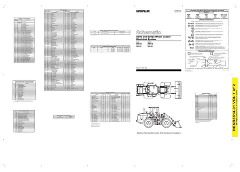
924G and 924Gz Wheel Loader Electrical System
Off Machine Switch Specification Part No.
Function
163-7355
Low Pressure
160-2609
High Pressure
Actuate
Deactuate
Contact Position A-C, Normally Closed
875 ± 20 kPa
517 kPa Min
(126 ± 2.9 psi)
(74 psi Min)
A-B, Normally Open
1724 kPa MAX
1325 ± 170 kPa
A-C, Normally Closed
(250 psi MAX)
(192 ± 24 psi)
A-B, Normally Open
924G: AAN1-UP 9SW1-UP 3PZ1-UP
MAGNETIC LATCH SOLENOID - A magnetic latch solenoid is an electrical component that is activated by electricity and held latched by a permanent magnet. It has two coils (latch and unlatch) that make electromagnet when current flows through them. It also has an internal switch that places the latch coil circuit open at the time the coil latches.
Harness and Wire Symbols
10
200-L32 BK-14
2 Ground Connection
Circuit Identification Number
C-12
E
C
Relay - Ride Control/load Check
C-12
E
A-7,8
1
Socket - Aux 24v
I-13
Control - FNR
A-4
A
Speedometer
¹ The CID is a diagnostic code that indicates which component is faulty.
Control - Secondary Steer
B-6
1
² The MID is a diagnostic code that indicates which electronic control module diagnosed the fault.
Converter - 12v to 24v DC
I-12
Coolant Temperature
E
0668
Shift Lever
Cigar Lighter
E-8
0683
Parking Brake Alarm
Control - CST Autoshift
0687
Invalid Option Code
A 6 C
14
E 12
2
1 9
Connector Location
8
CONN 1
Machine Location 12
CONN 2
A-15
12
CONN 3
A-15
12
5
CONN 4
A-15
12
H-2
A
CONN 5
B-15
12
Swicth - Kickout
G-10
D
CONN 6
B-15
12
2
Switch - Beacon
F-9
B
CONN 7
B-15
12
H-2
A
Switch - Blower
G-10
D
CONN 8
B-15
12
CST Shifter
I-3
A
Switch - Bucket Fork Select
G-10
D
CONN 9
C-15
12
Diode Block B
I-5
C
Switch - Defrost
G-10
D
CONN 10
D-15
5
Flasher
G-4
D
Switch - Dimmer
G-6
D
CONN 11
G-15
11
FNR - Relay
E-13
E
Switch - Downshift
B-12
D
CONN 12
F-14
4
F-2
A
Switch - Forward Horn
I-6
A
CONN 13
D-14
13 8
Fuel Level Gauge
Component Relay - Park Brake Alarm
Connector Number
13
G-2
A
Switch - Front Wiper
D-8
C
CONN 14 Harness Code Plug
E-10
Fuses
H-12,13
E
Switch - Hazard Lamp
G-9
B
CONN 15 Options Code
E-10
8
Fuses
G-12,13
E
Switch - Hyd Lock Detent Override
H-9
A
CONN 16 ECAP
D-10
8
Fuses
F-12
E
Switch - Key Start
G-6
A
CONN 17
F-6
14
Ground - Cab Boss
A-14
9
Switch - Parking Brake
I-13
5
CONN 18
F-6
14
Ground - Shell Stud
D-14
8
Switch - Quick Coupler
E-10
D
CONN 19
F-6
14
H-3
A
Switch - Rear Wiper
C-8
C
CONN 20
E-6
14
0
Data valid but above normal operational range.
Hydraulic Temperature Gauge
1
Data valid but below normal operational range.
Meter - Service
I-6
A
Switch - Ride Control
F-10
D
2
Data erratic, intermittent, or incorrect.
Motor - Blower
E-14
4
Switch - Secondary Steer
E-8
C
Motor - Front Wiper
F-2
6
Switch - Service Brake
E-3
10
Motor - Rear Defroster
F-15
4
Switch - Start Aid
F-9
B
Motor - Rear Wiper
F-15
7
Switch - Thermastat
E-14
D
11
7 4
A D E
10
B 5
CONN 21
E-6
14
CONN 22
H-5
14
6
CONN 23
H-5
14
14
CONN 24
B-4
15
CONN 25
A-4
15
CONN 26
A-4
15
C
2 1
3 12 13
9 8
6
Current above normal or grounded circuit.
Relay - Alarm Disarm A
C-13
E
Switch - Turn Hazard
G-5
A
7
Mechanical system not responding properly.
Relay - Alarm Disarm B
D-13
E
Switch - XMSN Auto Manuel
F-10
D
8
Abnormal frequency, pulse width, or period.
Relay - Backup Alarm
C-12
E
Switch - XMSN Neutralizer
F-9
B
Connectors that join a harness to a component are generally
9
Abnormal update.
Relay - Main Power
H-12
E
Torque Converter Temperature
G-3
A
located at or near the component. See the Component
10
Abnormal rate of change.
Machine locations are repeated for components located close togather.
11
Failure mode not identifiable.
A Located in the cab.
12
Bad device or component.
B Located in the lefthand console.
13
Out of calibration.
C Located in the righthand console.
14
Parameter failures.
D Located on or near relay panel.
15
Parameter failures.
E Located in or near relay panel
16
Parameter not available.
17
Module not responding. Sensor supply fault. Condition not met.
20
Parameter failures.
¹The FMI is a diagnostic code that indicates what type of failure has occurred.
15
The connectors shown in this chart are for harness connectors.
Location Chart.
Machine Harness Connector And Component Locations
Wire Gauge
Printed in U.S.A.
Schematic Location A-15
FNR LED Panel
19
Wire Color
15
B
Fuse (5 Amps) Component Part Number
D
Relay - Park Brake LT/Seat Alarm
H-13
18
9X-1123
11 5
Breaker - Air Seat
Current below normal or open circuit.
Pin or Socket Number
© 1999 Caterpillar All Rights Reserved
Harness Code
5
5A
Receptacle
Volume 1 of 2: Cab
Arc Suppressure
Form Number SENR1218
1
Harness identification code: This example indicates wire 135 in harness "AG".
Machine Location E
Title Transmission Control:
Part Number For Connector Recepticle
Plug
Connector Location
Related Electrical Service Manuals
L-C12 3E-5179
AG-C4 111-7898
Single Wire Connector
Schematic Location H-12
Voltage below normal or shorted low.
Harness Connector Serialization Code: The "C" stands for "Connector" and the number indicates which connector in the harness. (C1, C2, C3, .....)
325-AG135 PK-14 Socket
Pin
Sure-Seal connector: Typical representation of a Sure-Seal connector. The plug and receptacle contain both pins and sockets. Harness Identification Letter(s): (A, B, C, ..., AA, AB, AC, ...)
Part Number for Connector Plug
C-C4 AG-C3 130-6795 130-6795
Machine Location 3
Voltage above normal or shorted high.
1 2
Deutsch connector: Typical representation of a Deutsch connector. The plug contains all sockets and the receptacle contains all pins. Wire, Cable, or Harness Assembly Identification: Includes Harness Identification Letters and Harness Connector Serialization Codes
Component
4
Relay (Magnetic Switch): A relay is an electrical component that is activated by electricity. It has a coil that makes an electromagnet when current flows through it. The electromagnet can open or close the switch part of the relay. Solenoid: A solenoid is an electrical component that is activated by electricity. It has a coil that makes an electromagnet when current flows through it. The electromagnet can open or close a valve or move a piece of metal that can do work.
3
3
T
924Gz: AAB1-UP 6YW1-UP 3DZ1-UP
7
Failure Description
Sender: A component that is used with a temperature or pressure gauge. The sender measures the temperature or pressure. Its resistance changes to give an indication to the gauge of the temperature or pressure.
1 2
Schematic Location I-12
FMI No.
Circuit Breaker Symbol
Flow Symbol
Fuse - A component in an electrical circuit that will open the circuit if too much current flows through it.
4
Failure Mode Identifiers (FMI)¹
Level Symbol
Symbols and Definitions
Control Circuits
Ground Circuits
Temperature Symbol
Beacon
120
19
T
Pressure Symbol
Lighting Circuits
118
16
Symbols
COSA Flasher Output
Not Applicable
12
Harness And Wire Electrical Schematic Symbols
RENR3514-01 December 1999
Description
(Dimensions: 39 inches x 28 inches)
Wire Color
30 Page,
Wire Number
RENR3514-01 VOL 1 of 2
Description