RENR9695-02 March 2008
Harness And Wire Electrical Schematic Symbols Symbols T
Pressure Symbol
Temperature Symbol
Level Symbol
Circuit Breaker Symbol
Flow Symbol
Symbols And Definitions Fuse - A component in an electrical circuit that will open the circuit if too much current flows through it.
101
RD
Wire Color
Audible Alarm
G-1
A
Bat (+)
755
OR
XMSN Clutch #6 (1st Gear)
Beacon
I-15
40
Description Power Circuits
Control Circuits (Continued)
Machine Location
Schematic Location
Machine Location
Sensor - Throttle Position
F-2
11
Sensor - XMSN Neutralizer
G-2
11
Component
RD
Head Lamp
761
GY
Lift Kickout Sol SW
Breaker - Air Seat
G-11
E
Socket - 12V AUX
H-13
5
105
RD
Key SW
762
YL
Bucket Positioner Sol SW
Cluster - Instrument
G-1
A
Solenoid - Pilot Shutoff
C-8
D
108
RD
+12V Unswitched
779
WH
Quick Coupler Engage Sol
Control - Machine ECM
A-2 thru E-2
1
Solenoid - Quicksteer
E-2
1
PU
Quick Coupler Disengage Sol
Converter - 12V / 24V DC
H-12
E
Switch - A/C & Heater
E-8
D
WH
PWR 10 V Supply
CST Shifter
H-1
A
Switch - Auto / Manual / VSC
G-6
B
BU
Float Relay to Float Press SW
Defroster - Rear
G-15
7
Switch - Beacon
F-6
B
A700
OR
+8V Digital Sensor Power
Diode - Flasher (EURO)
H-5
A
Switch - Blower
D-8
D
Aux Breaker Output
A710
GY
Air Inlet restriction Switch
Diode - Japanese Beacon
G-6
B
Switch - Bucket / Fork Select
G-8
D
Main Breaker Output
A771
PU
Float SW
Diodes - Turn Signal (EURO)
H-5
A
Switch - Bucket Lower
C-8
D
Wipers
E701
PK
Auto Ride Cntl On SW
Flasher - (EURO)
I-5
A
Switch - Dimmer
E-6
B
8 Volt DC Supply
0091
Throttle Position Sensor
109
RD
Alt Output (+) Term.
780
0100
Engine Oil Pressure Sensor
110
GN
Turn Signal
799
0102
Boost Pressure Sensor
112
PU
Main Power Rly Output
B763
0105
Inlet Manifold Temperature Sensor
114
RD
Warning Horn (Forward)
0110
Engine Coolant Temperature Sensor
115
RD
117
RD
118
GY
Fuel Temperature Sensor
Component
102
0041
0174
Description
Schematic Location
0247
J1939 Data Link
120
YL
DC/DC Converter
E782
GN
Boom Float Press SW
Flasher - Japanese
I-6
A
Switch - Downshift
A-9
D
0253
Personality Module
122
RD
Dome Lights / Hour Meter
F700
BU
Tachometer
Flasher - US (NACD)
I-6
A
Switch - Front Wiper
H-4
C
0262
5 Volt Sensor Power Supply
123
WH
Coupler / MSS
F701
BR
Variable Flow SW To 3rd Function Solenoid
Fuses - Battery Power / Key Switch Off
E-12
E
Switch - Fwd Horn
F-1
A
0266
Crank Without Injection Input
124
GN
Blowers, A/C, Heater
E
Switch - Hazard Lamp
F-6
B
125
OR
Bat (+) Product Link
Throttle Position Sensor CAN Link (+)
F-12
Speed/Timing Sensor
GN GN
Fuses - Key Switch On
0320
F702 F711
Ground - Cab
B-15
9
Switch - Implement Disable
I-8
D
126
RD
Machine ECM
F712
GY
CAN Link (-)
Ground - Shell
G-15
88
Switch - Japanese Beacon
F-7
B
0342
Secondary Engine Speed Sensor
127
OR
Roof / Rear Floods
F716
WH
Throttle Lock Enable SW
Group - Pilot Valve
C-6, C-7
D
Switch - Key Start
G-1
A
0774
Secondary Throttle Position Sensor
128
PK
Kickouts
F717
YL
Throttle Lock Set SW
Lamp - Dome
H-14
45
Switch - Kickout On / Off
F-8
D
1627
Fuel Pump relay
129
BU
Cigar Lighter
F718
BU
Throttle Lock Set SW
Lamp - Rear Flood LH
I-15
41
Switch - Parking Brake
H-13
5
1639
Machine Security System Module
130
RD
Stop Lamp
F748
WH
Ride Ctrl Auto SW
Lamp - Rear Flood RH
I-15
42
Switch - Quick Coupler
H-8
D
1684
Fuel Injection Pump
131
BR
Flasher Diode
F765
BR
Park Brake SW Disengaged
Lamp - Roof Flood LH
I-1
43
Switch - Quicksteer
F-5
B
OR
Wiper / Boom / Spare
F766
WH
Kickouts/Detent Disable SW To Kickouts
I-1
43
Switch - Rear Intermittent Wiper
H-5
B
Engine Operation Mode Selector Switch
133
Lamp - Roof Flood LH (Atch)
1743
135
BU
+12V Switched
G728
YL
Implement Disable SW / 5th 6th Func Pwr
Lamp - Roof Flood RH
I-1
44
Switch - Rear Window Defrost
G-8
D
1894
Cruise Control Disengage Switch
136
GN
Secondary Steering
G732
WH
XMSN Inlet Temp
Lamp - Roof Flood RH (Atch)
I-1
44
Switch - Rear Wiper
G-4
C
1895
Cruise Control Speed Toggle Switch
140
BU
Rear Window Defroster
G743
OR
Japanese Beacon SW To Diode
Lighter - Cigar
F-5
D
Switch - Remote FNR
B-8
D
144
GN
Beacon / Heated Seat / Operator Presence
G748
PU
Quicksteer NC
Motor - Blower
I-12
12
Switch - Reversing Fan
F-8
D
150
RD
Engine ECM
G749
YL
Quicksteer NO
Motor - Front Wiper
H-7
6
Switch - Ride Control
F-8
D
158
BR
Condenser Motor
G750
BU
XMSN Shifter Fwd Input
Motor - Rear Wiper
H-15
7
Switch - Running Lamp
E-7
B
161
PK
Ride Control
G755
GY
XMSN Shifter Rev Input
Relay - Backup Lamp
D-12
E
Switch - Secondary Steer
G-5
C
Machine Control System (MID No. 081) CID
Component 8 Volt DC Supply
182
RD
Aux Breaker Output
G760
WH
XMSN Shifter 2nd Gear Input
Relay - Brake Lamp
D-12
E
Switch - Service Brake
D-7
B
0070
Parking Brake Switch
188
WH
Start Aid
G761
YL
XMSN Shifter 3rd Gear Input
Relay - Defroster
G-11
E
Switch - Thermostat
I-11
12
0096
Fuel Level Sensor
Tachograph / Spare
0041
198
RD
G762
BR
XMSN Shifter 4th Gear Input
Relay - Main Power
H-12
E
Switch - Throttle Lock Enable
H-8
D
199
RD
Aux Power Ground Circuits
G763
PU
XMSN Shifter Neutral Input
Relay - Reversing Fan
D-12
E
Switch - Throttle Lock Set
H-8
D
0177
Transmission Oil Temperature Sensor
G768
GN
XMSN Shifter 1st Gear Input
Relay - Ride Control
D-11
E
Switch - Turn Signal ( Japan)
I-6
A
0247
CAN Data Link
200
BK
Main Chassis
G787
GN
XMSN Shifter External Forward
Relay - Secondary Steer
C-12
E
Switch - Turn Signal (EURO)
I-5
A
0262
5 Volt Sensor Power Supply
201
BK
Instrument Cluster
G788
YL
XMSN Shifter External Reverse
Resistor - CAN Data Link Term 1
G-1
A
Switch - XMSN Neutralizer / Override
G-6
B
0271
Action Alarm
202
BK
Machine ECM
H702
PU
Reversing Fan Relay
Resistor - Heater Group
I-12
12
229
BK
Engine Ground
H704
PK
Impl Cont Reversing Fan Sol
Machine locations are repeated for components located close together.
H707
YL
Unused
A = Located in the center gage panel.
304
WH
H716
WH
Implement Control Solenoid Return
B = Located in left-hand dash panel.
0291
Demand Fan Solenoid
0367
Ride Control Switch
Basic Machine Circuits Starter Relay No. 1 Output
0368
Transmission & Variable Speed Control Switch
306
GN
Key SW To Machine ECM
J764
BR
Switch/Sensor Return #1
C = Located in right-hand dash panel.
0420
Secondary Steering
308
YL
Main Power Relay Coil
J766
PU
10 V RTN
D = Located in right-hand console.
0426
Brake Oil Pressure Sensor
310
PU
Thermal Start Relay Output
K748
OR
Secondary Steer Motor Relay
0444
Starter Motor Relay
321
BR
Backup Alarm Lamp Travel Alarm
K790
BU
Reversing Fan Switch (Auto)
322
GY
Warning Horn (Forward)
K791
OR
Reversing Fan Switch (Manual)
323
WH
Fuel Pump Relay Output
L740
BR
+5V Analog Sensor Return
YL WH
3rd Function Retract
0473
Brake Charging Pressure Sensor
0486
Fan Reversing Switch
325
PK
Fuel Pump Relay Coil
M739
0490
Pilot On / Off Switch
374
PK
Machine ECM To Start Relay Coil
P755
0585
Transmission Output Speed Sensor 1
375
BR
Thermal Start Relay Coil
P763
OR
3rd Function Extend
0590
Engine Electronic Control Module
377
OR
R799
BR
PWM Return 5-8
0600
Hydraulic Oil Temperature Sensor
Alternator (R) Term.
BR OR
PWM Return 11-12 PWM Return 9-12
Backup Alarm
GN
T799 X750
0637
403 417
GY
Primary Steer Pressure SW
X754
GN
Quick Steer Solenoid
0668
Shift Lever Input
428
OR
Opr Mon Xmsn Oil Temp
Y794
OR
Expanded CAN Data Link (+)
0672
Torque Converter Output Speed Sensor
442
GY
Hyd Oil Temperature Sensor
Y795
GN
Expanded CAN Data Link (-)
0673
Transmission Output Speed Sensor II
443
YL
TC Oil Temp Sensor
892
BR
CAT Data Link (-)
447
PK
Fuel Level Sender
893
GN
CAT Data Link (+)
453
PK
Secondary Steer Relay Output
C881
BU
Brake Charging Solenoid
483
BR
Brake Charging Oil Pressure
484
YL
Primary Steer Pressure SW
C885 H803
PK BU
Quick Steer SW Load Return 2 Load Return 1
0674
Transmission Intermediate Speed Sensor I
0675
Transmission Intermediate Speed Sensor II
0747
Quick Steer Switch
Thermal Start Resistor To Heater Monitoring Circuits
Primary Steering Pressure Switch
C444
YL
Alternator To Alternator Resistor
H807
YL
Gage Cluster #1
C446
PK
Axle Oil Pressure SW
X800
OR
+8V Sensor Power
E417
OR
Park Brake SW #2 (Engaged)
900
PU
XMSN Clutch #4 (2nd Gear)
901 944
WH OR
XMSN Clutch #5 (3rd Gear) CAT Data Link (+)
945
BR
CAT Data Link (-)
963
GN
Bucket/Fork Position Detent Coil Fork Position Select
0826
Torque Converter Oil Temperature Sensor
0882
Pilot On / Off Solenoid
1231
Brake Charging Solenoid
1251
Alternator R-Terminal Signal
1401
Clutch 1 Solenoid
500
BR
Wiper - Front (Park)
964
BU
1402
Clutch 2 Solenoid
501
GN
Wiper - Front (Low)
973
BR
CST Autoshift- Auto/Manual SW 2 - Manual
1403
Clutch 3 Solenoid
502
OR
Wiper - Front (HI)
975
WH
CST Autoshift- Sol Return
503
BR
Wiper - Rear (Park)
976
OR
Ride Cont Relay Output
1404
Clutch 4 Solenoid
504
YL
Wiper - Rear (Low)
977
YL
CST Autoshift- Auto/Manual SW 1 - Auto
1405
Clutch 5 Solenoid
505
BU
Wiper - Rear (HI)
978
GN
Downshift SW
1406
Clutch 6 Solenoid
506
PU
Washer - Front
993
BR
Sensor Common
1639
Machine Security System Module
507
WH
Washer - Rear
A975
BU
Differential Lock Solenoid
1834
Ignition Key Switch
508
PU
Radio Speaker - Left
C949
YL
XMSN Neutralizer Sensor
509
WH
Radio Speaker - Left (Common)
E900
WH
ECPC Trans Output SPD + / Tachograph
1960
Ignition Key Reader
511
BR
Radio Speaker - Right
E901
GN
ECPC Trans Output SPD -
2292
Quick Steer Solenoid
512
GN
Radio Speaker - Right (Common)
E902
PU
ECPC Trans Intermediate SPD +
¹ The CID is a diagnostic code that indicates which circuit is faulty.
515
GY
Blower Motor (HI)
E903
YL
ECPC Trans Intermediate SPD -
² The MID is a diagnostic code that indicates which electronic control module diagnosed the fault.
516
GN
Blower Motor (Medium)
E904
BR
ECPC Trans Intermediate SPD Q+
517
BU
Blower Motor (Low)
E905
BU
ECPC Trans Intermediate SPD Q-
518
OR
Hazard Flasher To SW
521
YL
A/C SW To Condenser Relay Coil
E906 E907
OR GY
ECPC Trans Output SPD Q+ ECPC Trans Output SPD Q-
522
WH
A/C Clutch To Thermostat SW
E908
BR
ECPC Trans Input SPD +
537
GN
Turn Signal SW To Flasher
E909
WH
538
BR
Hazard Indicator
E916
539
BU
Turn Signal Indicator Basic/Right
540
WH
Turn Signal Indicator Left
571
OR
589
GN
593 A504
Failure Mode Identifiers (FMI)¹ FMI No.
Failure Description
YL
Warning Switch to Alarm
BU
Hyd Oil Filter Bypass
H459
PU
Transmission Oil Filter Sw Accessory Circuits
74 12
A-15
18
CONN 2
B-15
18
ECPC Trans Input SPD -
CONN 3
B-15
18
OR
3rd Function MAX Flow SIG
CONN 4
C-15
18
E917
WH
Implement Lockout SW to Gnd (N.O.)
CONN 5
D-15
18
Ride Control Relay Coil
E918 E998
GN YL
Implement Lockout SW to Gnd (N.C.) Radiator Fan Solenoid
CONN 6
H-14
45
A/C Refrigerant Pressure SW
G942
OR
3rd Function Implement Lever
CONN 7
H-14
47
GN
Condenser Fan Relay To Motors
G962
OR
Kickout Solenoid
CONN 8
G-14
45
GN
Rear Window Defrost SW
G985
PU
Operator Presence SW
CONN 9
G-13
74
CONN 10
H-13
74
CONN 11
H-13
74 12
Connector Number
A507
YL
Rear Window Defrost Relay Coil
K927
BU
Quick Coupler Solenoid Return
A519
GN
Ride Control Solenoid
K952
BR
5th / 6th Function Handle Solenoid Return
A520
BU
Ride Control Relay Coil
L961
PU
Brake Neutralizer SW Indicator
A538
OR
Rear Window Defroster
M936
BR
Continuous Workflow
CONN 12
I-13
A541
PU
Flasher To Indicator Lights
M939
OR
Standard Worktool
CONN 13 Service Connector
C-8
D
A576
GN
Breaker To Compressor (Air Seat)
M998
OR
Transmission Autoshift Mode
CONN 14
D-8
D
CONN 15
F-1 , I-6 , I-7
A
CONN 16
B-8
B
PU
Heater or A/C SIG ON
N957
PK
RS-232 Port 1 - TXD
YL
Blower SW Jumper
N959
PK
RS-232 Port 3 - RXD
N960
OR
RS-232 Port 1 - RXD
N963
OR
RS-232 Port 3 - TXD
CONN 17
D-5
C
02
Data erratic, intermittent, or incorrect.
YL
RS-232 Port 1 - DTR
CONN 18
E-5
C
03
Voltage above normal or shorted high.
605
YL
Turn Lamp - Left
N973
BR
RS-232 Port 1 - DCD
CONN 19
E-5
C
04
Voltage below normal or shorted low.
606
GY
Turn Lamp - Right
N979
GN
RS-232 Port 1 - GND
CONN 20
A-3
1
608
GN
Flood Lamp - Rear
N981
GN
RS-232 Port 3 - GND
CONN 21
E-3
9 9
05
Current below normal or open circuit.
610
OR
Head Lamp Basic
P910
BR
Secondary Steering Test Sw Input
06
Current above normal or grounded circuit.
611
PU
Front Flood Lamps (Hi)
P914
GN
XMSN Forward Indicator
CONN 22
E-3
Mechanical system not responding properly.
612
GY
Backup Lamp
P915
PK
XMSN Neutral Indicator
CONN 23
F-3
9
08
Abnormal frequency, pulse width, or period.
614
PU
Park/Tail/Dash/Lamp
P916
OR
XMSN Shifter External Neutral
CONN 51
G-11
E
09
Abnormal update.
CONN 52
I-11
A
CONN 53
I-11
A
I-11
A
615
YL
Cab Flood Lamp / ROPS
P978
GN
Solenoid Control A
619
GN
Front Flood Lamps (Low)
P979
YL
Solenoid Control B
633
BU
+V Turn (Flasher) To Diode
P980
OR
Solenoid Control C
Failure mode not identifiable.
638
WH
Rotary Beacon
P981
PU
Solenoid Control D
CONN 54
Bad device or component.
665
BR
SW To Left Front / Right Rear Lights
R997
OR
+5V Analog Sensor Power
CONN 58
D-9
D
CONN 61
H-11
D
676
PU
Autoshift SW Indicator
T901
YL
MSS Exciter Coil In
677
GN
Service Brake SW
T902
PK
MSS Exciter Coil Out
691
GY
T930
WH
PL Sensor Power Supply (8.3 V)
T931
YL
PL Spare Digital Input #1
Parameter not available.
702
OR
Neutralizer Disable SW
T932
PK
PL Spare Digital Input #2
17
Module not responding.
727
GN
Suppl Steer Motor Relay Coil
T933
PU
PL Multipurpose Input #1
18
Sensor supply fault.
751
GN
XMSN Clutch #2 (Fwd High Gear)
T934
OR
PL Multipurpose Input #2
19
Condition not met.
752
YL
XMSN Clutch #1 (Fwd Low Gear)
T935
BU
PL Spare Digital Input #3
XMSN Clutch #3 (Rev Gear)
GN
PL Spare Digital Input #4
Not Used
BU
T936
20
754
16
Flasher To Diode Control Circuits
Harness Connector Serialization Code: The "C" stands for "Connector" and the number indicates which connector in the harness. (C1, C2, C3, .....)
L-C12 3E-5179
AG-C4 111-7898 1
5A
Socket Receptacle Pin or Socket Number
200-L32 BK-14
2 Ground Connection
Circuit Identification Number
B
E
C 6
5 1
9
11
88
18
V-LINK 40
41 42
43
47
44
45
7 A D 74 12
The connectors shown in this chart are for harness to harness connectors. Connectors that join a harness to a component are generally located at or near the component. See the Component Location Chart.
6
5 1
18
C
B
E
9
11
88
1
41
43
5
B
Resistor, Sender and Solenoid Specifications
Related Electrical Service Manuals Alternator: Electric Starting Motor: Engine Control: Machine Control:
Part No.
Form Number SENR4130 SENR3828 RENR2417 RENR6423
Off Machine Switch Specification Part No. 3E-5464
Function Refrigerant Thermostat
Actuate -1.1 ± 0.8°C (30 ± 1.4°F)
Deactuate 2.2 ± 0.8°C (36 ± 1.4°F)
Wire Color
Wire Gauge
Printed in U.S.A.
44
45
Z-BAR
177-9953 (80A) 197-8820 95A) 143-0451
9X-1123
Fuse (5 Amps) Component Part Number
¹The FMI is a diagnostic code that indicates what type of failure has occurred.
Title
Part Number For Connector Recepticle
43
47
Connector Location - Cab
CONN 1
E529
40
D
Machine Location
E528
Harness Identification Letter(s): (A, B, C, ..., AA, AB, AC, ...)
Wire, Cable, or Harness Assembly Identification: Includes Harness Identification Letters and Harness Connector Serialization Codes Part Number for Connector Plug
Sure-Seal connector: Typical representation of a Sure-Seal connector. The plug and receptacle contain both pins and sockets.
A
N970
Not Used
924Gz: WGX648-UP
1 2
Deutsch connector: Typical representation of a Deutsch connector. The plug contains all sockets and the receptacle contains all pins.
7
Stop Lamp
15
1 2
42
Rotary Beacon
Out of calibration.
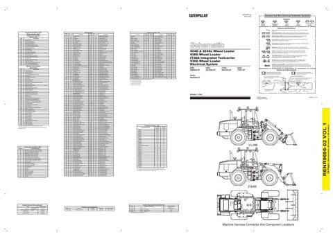
Harness And Wire Symbols
41
PK
Not Used
930G: TFW1-UP
© 2008 Caterpillar All Rights Reserved
OR
14
MAGNETIC LATCH SOLENOID - A magnetic latch solenoid is an electrical component that is activated by electricity and held latched by a permanent magnet. It has two coils (latch and unlatch) that make electromagnet when current flows through them. It also has an internal switch that places the latch coil circuit open at the time the coil latches.
Harness identification code: This example indicates wire 135 in harness "AG".
604
13
IT28G: WAC494-UP
Solenoid: A solenoid is an electrical component that is activated by electricity. It has a coil that makes an electromagnet when current flows through it. The electromagnet can open or close a valve or move a piece of metal that can do work.
Plug
603
12
928G: WLG590-UP
Relay (Magnetic Switch): A relay is an electrical component that is activated by electricity. It has a coil that makes an electromagnet when current flows through it. The electromagnet can open or close the switch part of the relay.
Single Wire Connector
Data valid but below normal operational range.
11
924G: WMB655-UP
Sender: A component that is used with a temperature or pressure gauge. The sender measures the temperature or pressure. Its resistance changes to give an indication to the gauge of the temperature or pressure.
T
E = Located in or near relay panel.
01
Abnormal rate of change.
924G & 924Gz Wheel Loader 928G Wheel Loader IT28G Integrated Toolcarrier 930G Wheel Loader Electrical System
325-AG135 PK-14
Data valid but above normal operational range.
10
Reed Switch: A switch whose contacts are controlled by a magnet. A magnet closes the contacts of a normally open reed switch; it opens the contacts of a normally closed reed switch.
Pin
00
07
Ground (Case): This indicates that the component does not have a wire connected to ground. It is grounded by being fastened to the machine.
C-C4 AG-C3 130-6795 130-6795
Schematic Location
Lighting Circuits
Ground (Wired): This indicates that the component is connected to a grounded wire. The grounded wire is fastened to the machine.
Volume 1 - Cab
0811
H458
Switch (Normally Closed): A switch that will open at a specified point (temp, press, etc.). No circle indicates that the wire cannot be disconnected from the component.
Quick Coupler Solenoid Return
0793
H414
Switch (Normally Open): A switch that will close at a specified point (temp, press, etc.). The circle indicates that the component has screw terminals and a wire can be disconnected from it.
Contact Position Normally Closed
Component Description
9G-1950
Resistor:
A/C
212-1305
Solenoid:
Pilot Valve Gp
225-0300
Solenoid:
Pilot Valve Shutoff
247-4503
Solenoid:
Quicksteer
¹ At room temperature unless otherwise noted.
40
7
A
45
6
Resistance (Ohms)¹ Overall: 2 ± 0.1 Between Taps: 1 ± 0.05
74
C
76.3 ± 3.8 25 ± 5 35 ± 1.8
D 42 12 18 47
11
E 9
88
44
Machine Harness Connector And Component Locations
(Dimensions: 39 inches x 28 inches)
Component
Wire Color
Component Location - Cab
Wire Number
30 Page,
CID
Wire Description Wire Number
RENR9695-02 VOL 1
Component Identifiers (CID¹) Module Identifier (MID²) Engine Control System (MID No. 036)