Component
0041 0070 0138 0168 0190 0191 0363 0367 0378 0379 0444 0562 0590 0603 0623 0626 0627 0628 0650 0670 0672 0678 0679 0826 1022 1401 1402 1403 1404 1405
¹ The CID is a diagnostic code that indicates which circuit is faulty. ² The MID is a diagnostic code that indicates which electronic control module diagnosed the fault.
Failure Mode Identifiers (FMI)¹ Failure Description
Wire Color
+ Battery
622
PU
Flood Lamp 3 Way Jumper 1
Power Circuits RD
Flood Lamp Power
623
BU
Flood Lamp 3 Way Jumper 2
BR
Key Sw Power
625
PK
RH Dash Lamp
106
WH
Main Relay Power
637
GN
T/C Lock Up Indicator Lamp
108
BU
Seat Compressor Power
641
OR
Stairway Lamp
109
RD
Alt Output & Start Relay Power
646
OR
Front Flood Sw To Relay
112
PU
Main Relay Power Output
651
PK
Rear Cab Floods
113
OR
Monitor System Power
661
GN
Tachometer Backlight
114
RD
Forward Horn Power
662
YL
Speedometer Lamp
117
YL
Stairway / Service Lamp Power
663
GY
Gage Lamps
118
GY
Wiper Motor Power
679
GY
Reduced Rimpull Indicator
119
PK
Left And Right Wiper Power
680
GN
Front Fender HID Floods
120
YL
Bucket Flood & Volt Conv Sw Power
A625
BR
Fender Flood Relay To Hid Relay
124
GN
Blower Motor Power
A629
BU
135
BU
12v Power
Front Rops HID Flood Control Circuits
142
BU
Front Fender Flood Power
709
OR
Xmsn ECM +12v Sensor Supply
143
BR
Front Cab Flood Power
710
GN
Xmsn Output Speed
144
GN
Rear Floods Power
751
GN
Clutch 1 Reverve
145
BU
Front Cab HID Flood Power
752
YL
Clutch 2 Forward
146
GY
Implement System Power
754
BU
Clutch 3 Speed 4
147
PU
Rear Cab Floods Power
755
OR
Clutch 4 Speed 3
150
RD
Engine ECM Power
761
GY
Lift Kickout Sol Sw
156
YL
Front Fender HID Power
762
YL
Bucket Positioner Sol Sw
164
WH
Powertrain System Power
A700
OR
Eng +8v Pwr
171
GN
Beacon Power
E701
PK
Ride Control Sw
179
BU
Aux Ckt
E705
BU
Impeller Clutch Press
185
RD
24v To 12v Converter Unswitched Power
E707
GN
188
WH
Payload Control System Power
E708
PK
CONN 8
F-13
G-7, G-19
CONN 9
G-13
F-7, F-20
CONN 10
H-13
J-6, J-20
CONN 11
I-13
I-6, I-21
CONN 12
F-12
M-6, M-22
CONN 13
C-12
F-7, F-18
CONN 14
B-12
F-5, F-19
CONN 15
A-12
F-5, F-19
CONN 16
D-11
K-8, K-17
CONN 17
E-11
K-7, K-19
CONN 18
F-11
J-8, J-18
Throttle Peddle
CONN 23
Aux Start Receptacle
200
BK
Main Chassis Ground
F706
PU
Throttle Lock Indicator
CONN 24
201
BK
Monitoring System Ground
F715
PU
Ground Level Shutdown
CONN 25
202
BK
Xmsn ECM Digital Return
F716
WH
Ground Level Shutdown
CONN 26
F-5
229
BK
Engine ECM Ground
F717
YL
Thottle Lock Set
CONN 27
F-4
K-8, K-17
Throttle Lock Resume
CONN 28
I-6
N-8, N-22
BK
Payload Monitor Cust Gnd
F718
BU
A-8
K-8, K-16
F-7
J-8, J-17 K-8, K-17
251
BK
Payload Monitor - Sys Gnd
F719
BR
Throttle Lock On/off
CONN 29
I-4
N-8, N-22
290
BK
CMS Service
F721
GY
RH Brake Pedal N.C.
CONN 30
I-3
291
BK
CMS Clear
F722
OR
RH Brake Pedal N.O.
CONN 31
C-3, G-3
A235
BK
Digital Sensor Return
F741
WH
Impeller Clutch Resume Sw
CONN 32
I-2
N-8, N-22 O-6, O-20 P-7, P-24 S-7, S-23
A273
BK
G747
OR
Xmsn LUC Prop Sol
G748
PU
Steer/Xmsn Lock N.O.
CONN 33
E-2
CONN 34
C-2
CONN 35
C-2
Xmsn ECM Ground Basic Machine Circuits
Xmsn Sw (Second Gear)
CONN 40
G-1
R-8, R-18
321
BR
Backup Alarm
G761
YL
Xmsn Sw (Third Gear)
CONN 41
G-1
R-7, R-22
322
GY
Forward Horn
G762
BR
Xmsn Sw (Fourth Gear)
CONN 42
F-1
Q-7, Q-20
326
PU
Key Switch Off Position
G763
PU
Xmsn Neutral Sw
338
PK
G764
PK
Xmsn ECM Park Brake Pos Sw
G765
GN
T/C Lockup Enable
403
GN
Alternator 'R' Terminal
G766
GN
Ride Control Sw N.C.
410
WH
Mon Sys Action Alarm
G767
WH
Ride Control Sw N.O.
411
PK
Mon Sys Master Action Lamp
G768
GN
Xmsn Upshift Sw
417
GY
Primary Steering Press Sw
G794
OR
Xmsn Quickshift Ind Lamp
419
YL
Parking Brake Press Switch
H722
GN
Decelerator Pedal Position
426
BR
Xmsn Filter Bypass Sw 2
H724
YL
Xmsn Impeller Clutch Sol
429
YL
Brake Oil Temp
H746
YL
Demand Fan Sol +
Atmospheric Press Sensor
WH
Steering Oil Temp
R747
GY
YL
Mon Sys Display Data
T725
WH
Fuel Filter Sw
C414
BU
Mon Sys Display Load
T746
PK
Turbo Outlet Press Sensor
C491
PU
Park Brake Pressure
801
PK
Auto Lube Sol
F417
YL
PMS Store Sw
818
BR
Serial Data Tx
F421
YL
Fuel Temp
819
GY
Serial Data Rx
H471
GY
Auto Lube Warning Indicator Accessory Circuits
4
Voltage below normal or shorted low.
500
BR
5
Current below normal or open circuit.
501
GN
6
Current above normal or grounded circuit.
502
OR
7
Mechanical system not responding properly.
503
BR
8
Abnormal frequency, pulse width, or period.
504
YL
893
GN
Cat Data Link (+)
A893
OR
Fuel Priming Switch To Pump
Wiper Front (Park)
G828
WH
Engine ECM Pressure Sensor +5v
Wiper Front (Low)
G829
GN
Engine ECM Pressure Sensor Common
Wiper Front (Hi)
G833
PK
Engine Temperature Sensor Common
Wiper Rear (Park)
G856
WH
TDC Probe +
Wiper Rear (Low)
G857
YL
TDC Probe -
9
Abnormal update.
505
BU
Wiper Rear (Hi)
J842
BK
Digital Return
10
Abnormal rate of change.
506
PU
Front Washer
T858
GY
Injector High Side
11
Failure mode not identifiable.
507
WH
Rear Washer
T859
WH
Injector High Side
12
Bad device or component.
508
PU
Radio Speaker Left
T860
OR
Injector High Side
509
WH
Radio Speaker Left (Common)
900
PU
Clutch 5 Speed 2
14
Parameter failures.
511
BR
Radio Speaker Right
975
WH
Xmsn ECM Sol Return
15
Parameter failures.
512
GN
Radio Speaker Righ (Common)
976
OR
Ride Control Sol
16
Parameter not available.
513
OR
Ac Refrigerant Press
994
GY
Eng Oil Press
17
Module not responding.
515
GY
Blower Motor (Hi)
995
BU
Engine Coolan Temp
18
Sensor supply fault.
516
GN
Blower Motor (Medium)
998
BR
Engine Digital Rtn
19
Condition not met.
517
BU
Blower Motor (Low)
C967
BU
Inlet Air Temp
20
Parameter failures.
521
YL
A/C Refrigerant Sw
C985
BU
Xmsn ECM +8v
522
WH
A/C Clutch Sol
C991
PK
Fuel Filter Monitor
523
BR
Wiper - Left (Park)
E955
OR
PCS Keypad Data
524
BU
Wiper - Left (Low)
E963
BK
Engine Speed/Timing A-
525
GY
Wiper - Left (Hi)
E964
WH
Engine Speed/Timing A+
526
YL
Wiper - Right (Park)
E965
BU
Engine Speed/Timing B-
527
GN
Wiper - Right (Low)
E966
YL
Engine Speed/Timing B+
528
PK
Wiper- Right (Hi)
E985
BR
Autolube
529
WH
Washer Left
E987
WH
Engine Speed Signal Return
545
WH
Single Tilt Switch To Relay
E988
PU
Rimpull Sw 1
553
YL
Dual Tilt Sw to Pitch Sol
E989
WH
Rimpull Sw 2
554
PK
Dual Tilt Sw to Single Tilt Sol
G939
PK
Torque Conv Speed Sensor Rtn
555
OR
Trigger Sw to Toggle- Dual Tilt
G960
WH
Pilot Cutout Switch #1
A513
PK
DC/DC Converter Memory Out
K983
BU
Monitor Sys 8v Sensor Supply
A524
BR
Temp Pot Pos 2
L919
YL
Manual Lube Sw
A528
YL
Electronic Water Valve Actuator
N957
PK
Rxd - Comm #1
A557
WH
Cab Air Precleaner
N960
OR
Txd - Comm #1
C529
GY
Lift Head End Press Sensor
N970
YL
Dtr - Comm #1
C530
BU
Lift Position Sensor
N973
BR
Dcd - Comm #1
C532
GN
Autolube Press Lighting Circuits
N979
GN
Signal Gnd - Comm #1
P911
PU
Rimpull Sw Input 3
600
BR
Dash/Tail Lamp
P912
BU
Rimpull Sw Input 4
603
PK
Rotary Beacon
R971
YL
Transmission Lube Temp
604
OR
Stop Lamp
T957
PU
Inj 1 Return
607
PK
Flood Lamp-front
T958
YL
Inj 2 Return
608
GN
Rear Flood Lamp
T959
BR
Inj 3 Return
610
OR
Head Lamp-Basic
T960
BU
Inj 4 Return
615
YL
Front Cab Flood Lamp
T961
GN
Inj 5 Return
Form Number
616
BU
Bucket Flood Lamp
T962
WH
Inj 6 Return
620
WH
Engine Service Lamp
E-12
E-5, E-19
Solenoid - Auto Lube
Diode - Blocking (1)
B-4
L-8, L-16
Solenoid - Demand Fan
Diode - Blocking (2)
B-4
L-8, L-16
Solenoid - Dual Tilt
Diode - Blocking (3)
B-4
L-8, L-16
Solenoid - Impeller Clutch
Fuse - Alternator
I-13
H-5, H-19
Solenoid - L.U.C.
G-12
K-6, K-20
Fuse Panel
D-9
M-8, M-16
F-1
Q-7, Q-20
Junction Block (1)
D-11
J-8, J-17
Solenoid - Start Aid
C-12
F-7, F-18
Junction Block (2)
D-11
J-8, J-17
Solenoids - Cylinder Head 1,3,5,7,9,11
G-15
G-7, G-19
Solenoid - Ride Control
I-9
J-9, J-18
E-11
K-6, K-21
B-2
W-6, W-24
H-12
K-6, K-20
Motor - Fuel Priming Pump
E-14
E-7, E-21
Solenoids - Cylinder Head 2,4,6,8,10,12
G-13
Motor - Starter
I-12
I-5, I-19
Solenoids - Transmission
H-11
L-6, L-20
Motor - Starter (Atch)
I-13
I-5, I-22
Switch - A/C Pressure
E-12
E-5, E-19
Relay - Backlight
C-4
L-8, L-16
Switch - Auto Lube Grease Level
H-9
J-9, J-18
Relay - Fender HID HAL
C-5
K-8, K-16
Switch - Brake Oil Pressure
D-12
O-7, O-18
Relay - Front Fender Flood
C-5
K-8, K-16
Switch - Bucket Positioner
G-1
Y-8, Y-19
Relay - Horn
C-4
L-8, L-16
Switch - Disconnect
I-10
E-4, E-24
Sensor - Camshaft Speed Timing
E-14
E-7, E-21
Switch - Primary Steering Pressure
F-12
M-6, M-22
Sensor - Coolant Temperature
E-14
E-7, E-19
Switch - Steering Oil Temperature
F-12
N-6, N-22
Switch - Transmission Oil Filter Bypass
H-9
K-8, K-20
Sensor - Crankshaft Speed Timing
E-14
E-5, E-18
Sensor - Engine Oil Pressure
D-14
E-7, E-20
T
Pressure Symbol
Temperature Symbol
Level Symbol
Circuit Breaker Symbol
Flow Symbol
Symbols And Definitions Fuse - A component in an electrical circuit that will open the circuit if too much current flows through it. Switch (Normally Open): A switch that will close at a specified point (temp, press, etc.). The circle indicates that the component has screw terminals and a wire can be disconnected from it. Switch (Normally Closed): A switch that will open at a specified point (temp, press, etc.). No circle indicates that the wire cannot be disconnected from the component. Ground (Wired): This indicates that the component is connected to a grounded wire. The grounded wire is fastened to the machine. Ground (Case): This indicates that the component does not have a wire connected to ground. It is grounded by being fastened to the machine.
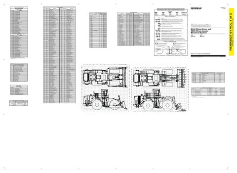
844H Wheel Dozer and 990H Wheel Loader Electrical System
Reed Switch: A switch whose contacts are controlled by a magnet. A magnet closes the contacts of a normally open reed switch; it opens the contacts of a normally closed reed switch. Sender: A component that is used with a temperature or pressure gauge. The sender measures the temperature or pressure. Its resistance changes to give an indication to the gauge of the temperature or pressure.
T
F-7, F-20
O-7, O-20
WH
A451
Solenoid - A/C Compressor
K-8, K-16
O-7, O-20
G760
C413
K-8, K-16
A-6
H-10
Horn Relay Coil to Sw
Engine Digital Sensor Return
C-8
Control - Power Train
G-12
OR
Turbo Outlet Press Sensor
Control - Gateway
Switch - Park Brake Pressure
320
PK
N-4, N-21
Switch - Park Brake
Z-8, Z-22
PU
G-10
F-7, F-20
Y-8, Y-19
N707
Sensor - Transmission Output Speed
R-7, R-20
A-2
R746
F-7, F-21
H-1
H-1
Engine Speed (-)
F-15
D-14
CONN 39
Torque Converter Temp
Control - Engine ECM
Sensor - Atmospheric Pressure
CONN 38
BR
K-6, K-19
Sensor - Auto Lube Pressure
Quickshift Sw (N.C.)
PU
K-6, K-20
G-12
J-3, J-20
Z-8, Z-26 Q-6, Q-19 T-7, T-23 Z-8, Z-22
Quickshift Sw (N.O.)
452
H-12
Sensor - T/C Output Speed
R-8, R-22
E-4, E-24
PU
451
Sensor - T/C Oil Outlet Temperature
E-4, E-19
G-1 E-12
R-8, R-18
WH
Engine Retarder Sol 3,4
M-8, M-17
I-10
Sensor - Lift Linkage Position Sensor - Rear Axle Oil Temperature
G-1
G759
Engine Retarder Sol Common
B-10
Bus Bar
Q-7, Q-19
I-15
G758
BU
Breaker - Starter Solenoid
F-7, F-20
G-1
Switch - Lift Kickout
Start Relay No 2 Output
GN
M-8, N-17
E-14
Sensor - Lift Cylinder Head End Pressure
Switch - Ground Level Stairway Lamp
Start Aid Sol to Temp Sw
K738
M-8, M-17
C-10
Sensor - Intake Manifold Air Temperature
M-8, M-16
L-8, L-17
PU
K739
B-10
Breaker - Running Lamp
M-8, M-16
M-2, M-24
WH
Fuel Level
Breaker - Main
F-7, F-20
F-12
314
Engine Speed (+)
C-10
N-7, N-17
C-10
311
YL
B-10
Breaker - Key Switch
D-12 D-14
Sender - Fuel Level
B-2
PK
Breaker - Engine Control
Sensor - Implement Oil Temperature Sensor - Intake Air Pressure
Relay - Secondary Starter
CONN 37
447
C-3, C-16, C-23
Z-8, Z-26
Park Brake Press Sw N.O.
450
F-5, F-19
I-11
S-7, S-17
YL
Engine Retarder Sol 3 4
E-12
E-4, E-24
G756
Engine Retarder Sol Cyl 1 2 5 6
Arc Supressor - A/C Bateries
E-7, E-22
Main Power Relay On
BR
K-5, K-20
I-15
YL
GN
H-13
Switch - Ground Level Shutdown
308
J701
E-8, E-21
Sensor - Impeller Clutch Pressure
K-8, K-16
F-1, B-2
K737
W-6, W-24
C-5
CONN 36
Torq Conv Oil Temp
C-2
Relay - ROPS HID HAL
Xmsn Reverse Sw
Rear Axle Temp
Arc Supressor - (4)
E-7, E-21
GY
YL
E-8, E-21
F-14
I-15
G755
PU
F-14
Sensor - Fuel Temperature
Switch - Fuel Priming Pump
Key Sw Nuetral Start
446
Sensor - Fuel Pressure
L-8, L-17
OR
443
W-6, W-24
C-10
307
Demand Fan Sol -
E-6, E-19
B-2
Relay - Primary Steering
Steer/Xmsn Lock N.C.
Engine Retarder Sol Cyl 1 2 5 6
I-13
Arc Supressor - (3)
E-5, E-22
Xmsn Forward Sw
BR
Alternator
I-15
YL
BR
U-3, U-20
F-14
BU
J700
F-1
Switch - Fuel Differential Pressure
G749
H747
Sensor - Front Axle Oil Temperature
Switch - Engine Service Lamp
G750
Brake Press.
B-8, B-18
L-8, L-16
Xmsn Neutral Start
Hydraulic Tank Oil Temperature
E-15
K-8, K-17
Starter Sol 'S' Term
PK
Alarm - Back Up
C-4
GN
GY
Machine Location
B-10
WH
432
Schematic Location
Component
Relay - Main
306
442
Machine Location
Relay - HVAC Precleaner
304
Flood Lamp Relay Monitoring Circuits
Schematic Location
Component
M-6, M-22
I-8
Operator Mode Switch
Data erratic, intermittent, or incorrect.
RENR8811
E-7, E-20
PU
Voltage above normal or shorted high.
RENR9317
E-7, E-21
F-13
GN
3
Engine Control:
E-7, E-20
C-13, F-13
F702
2
Transmission Control:
D-14
CONN 7
E735
Transmit Key
SENR3860
F-7, F-20
CONN 6
Cab Air Precleaner Power Ground Circuits
Cat Data Link (-)
237-1962 (Delco 50MT)
CONN 5
E-14
E-5, E-22
BU
Electric Starting Motor:
TDC Probe
D-4, D-18
BR
SENR4130
CONN 4
I-9
820
226-7683 (Denso HDB)
I-7, I-18
I-8
892
Alternator:
H-14
CONN 22
Autolube Low Level Sw (N.O.)
Title
CONN 3
CONN 21
Secondary Steering Indicator
Related Electrical Service Manuals
E-6, E-22
Mon Sys Display Clock
PK
High Fuel Pressure High Exhaust Temperature User Defined Shutdown Low Engine Oil Pressure High Engine Coolant Temperature Engine Overspeed High Fuel Temperature Fuel Filter Restriction Idle Elevated to Increase Battery Voltage High Intake Manifold Air Temperature
E-4, E-20
H-14
N-7, N-18
PU
E096 E194 E265 E360 E361 E362 E363 E390 E441 E539
I-14
CONN 2
G-9
H420
Condition
CONN 1
CONN 20
G438
Event Code
Machine Location
Mon Sys Display +v
Data valid but below normal operational range.
Event Codes Engine Control
Schematic Location
Connector Number
M-6, M-19
Data valid but above normal operational range.
¹The FMI is a diagnostic code that indicates what type of failure has occurred.
Component Location
Connector Location
H-10
1
Out of calibration.
Symbols
CONN 19
0
13
Harness And Wire Electrical Schematic Symbols
Lighting Circuits
102
YL
RENR8827-01 July 2008
Description
105
250
8 V DC Supply Parking Brake Switch Reduced Rimpull Selector Switch Electrical System Voltage Engine Speed Sensor Transmission Output Speed Sensor Ride Control Solenoid 1 Ride Control Switch Autolube Solenoid Autolube Pressure Sensor Starter Motor Relay Caterpillar Monitoring System Engine Control ECM Impeller Clutch Pressure Sensor Directional Switch Steering Lock Switch Park Brake Pressure Switch Quick Shift Switch Harness Code LH Brake Pedal Sensor T/C Output Speed Sensor Impeller Clutch Solenoid Lock Up Clutch Solenoid T/C Oil Outlet Temperature Sensor Autolube Grease Level Switch Transmission Solenoid #1 Transmission Solenoid #2 Transmission Solenoid #3 Transmission Solenoid #4 Transmission Solenoid #5
FMI No.
RD
195
Electronic Transmission Control System (MID No. 081) CID
101
Wire Number
Description
Relay (Magnetic Switch): A relay is an electrical component that is activated by electricity. It has a coil that makes an electromagnet when current flows through it. The electromagnet can open or close the switch part of the relay.
844H: BTW1-UP
Solenoid: A solenoid is an electrical component that is activated by electricity. It has a coil that makes an electromagnet when current flows through it. The electromagnet can open or close a valve or move a piece of metal that can do work.
990H: BWX1-UP
MAGNETIC LATCH SOLENOID - A magnetic latch solenoid is an electrical component that is activated by electricity and held latched by a permanent magnet. It has two coils (latch and unlatch) that make electromagnet when current flows through them. It also has an internal switch that places the latch coil circuit open at the time the coil latches.
Harness And Wire Symbols 1 2
1 2
Deutsch connector: Typical representation of a Deutsch connector. The plug contains all sockets and the receptacle contains all pins.
Harness Identification Letter(s): (A, B, C, ..., AA, AB, AC, ...)
Wire, Cable, or Harness Assembly Identification: Includes Harness Identification Letters and Harness Connector Serialization Codes
Harness Connector Serialization Code: The "C" stands for "Connector" and the number indicates which connector in the harness. (C1, C2, C3, .....)
Part Number for Connector Plug
C-C4 AG-C3 130-6795 130-6795
Sure-Seal connector: Typical representation of a Sure-Seal connector. The plug and receptacle contain both pins and sockets.
L-C12 3E-5179
AG-C4 111-7898
Part Number For Connector Recepticle
1
325-AG135 PK-14
5A
Socket
Pin
Receptacle Pin or Socket Number
Single Wire Connector
9X-1123
Component Part Number
Plug
200-L32 BK-14
2
Harness identification code: This example indicates wire 135 in harness "AG".
Fuse (5 Amps)
Circuit Identification Number
Ground Connection
Wire Color
Volume 1 of 2: Chassis and Engine Wiring Wire Gauge
© 2008 Caterpillar, All Rights Reserved
a
b
c
d
e
f
g
h
i
j
k
l
m n
o
p
q
r
s
t
u
v
w
x
y
z aa bb cc dd ee ff
32
32
31
31
30
30
29
29
28
a
b
c
d
e
f
g
h
i
j
k
l
m n
o
p
q
r
s
t
u
v
w
x
y
z aa bb cc dd ee ff
25
25
28
24
24
27
27
23
23
26
26
22
Resistor, Sender and Solenoid Specifications Part No.
Component Description
22
Solenoid:
Ride Control
32.6 ± 1.6
183-5106
Solenoid:
A/C Compressor Clutch
17.6±0.6
21
183-7595
Solenoid:
Demand Fan
5.0 ± 0.3
216-5342
Solenoid:
Lockup Clutch
8.7 ± 0.4
239-1134
Solenoid:
Start Aid
245-7465
Solenoid:
Impeller Clutch
7.75 ± 1.0
253-0617
Solenoids:
Injectors
1.06 ± 5%
256-6453
Sender: Solenoids:
Transmission Clutch
8.15 ± 0.6
3E-9205
Solenoids:
Dual Tilt
24.9 ± 0.4
25
24
24
23
23
22
22
19
21
21
18
18
302-3811
20
20
17
17
¹ At room temperature unless otherwise noted.
19
19
16
16
18
18
17
17
15
15
16
16
14
14
15
15
13
13
14
14
12
12
13
13
11
11
12
12
11
11
10
10
10
10
9
9
9
9
8
8
8
8
7
7
7
7
6
6
6
6
5
5
5
5
4
4
4
4
3
3
3
3
2
2
2
2
1
1
1
1
b
c
d
e
f
g
h
i
j
k
l
m n
o
p
q
r
s
t
u
v
w
x
y
z aa bb cc dd ee ff gg
21 20
20 19
b
c
d
e
f
g
h
i
j
k
l
m n
o
p
q
r
s
t
u
v
w
x
y
z aa bb cc dd ee ff
6
Fuel Temperature
1000
Off Machine Switch Specification Part No.
Function
Actuate
Deactuate
Contact Position
275 to 1750 kPa¹ Normally Open² 114-5333 A/C (High / Low) Pressure (39.9 to 253.8 psi) 102 ± 3 C° 90 C° MIN 131-4135 Steering Oil Temperature Normally Closed (215.6 ± 5.4 F°) (194 F° MIN) A-B, Normally Open Brake Oil Pressure 8270 kPa MAX 6890 ± 345 kPa 174-4312 A-C, Normally Closed Park Brake Pressure (1200 psi MAX) (1000 ± 50 psi) 110.3 ± 13.8 kPa 69 kPa MIN 275-1253 Fuel Differential Pressure Normally Closed (16 ± 2 psi) (10 psi MIN) A-B Normally Open 1200 kPa MAX 700 ± 100 kPa 3E-6450 Primary Steering Pressure A-C Normally Closed (174.0 psi MAX) (102 ± 14.5 psi) ¹ With increasing pressure the closed condition can be maintained up to 2800 kpa (405 psi), with decreasing pressure the closed condition can be maintained down to 170 kpa (25psi). ² Contact postion at the contacts of the harness connector.
a
Resistance (Ohms)¹
152-8340
25
a
Printed in U.S.A.
(Dimensions: 48 inches x 35 inches)
Component Fuel Injector Solenoid #1 Fuel Injector Solenoid #2 Fuel Injector Solenoid #3 Fuel Injector Solenoid #4 Fuel Injector Solenoid #5 Fuel Injector Solenoid #6 Fuel Injector Solenoid #7 Fuel Injector Solenoid #8 Fuel Injector Solenoid #9 Fuel Injector Solenoid #10 Fuel Injector Solenoid #11 Fuel Injector Solenoid #12 ECM 8V DC Supply Throttle Sensor Fuel Pressure Sensor Oil Pressure Sensor Engine Coolant Temperature Sensor Electrical Power Supply Intake Manifold Air Temperature Sensor Fuel Temperature Sensor Engine Speed Sensor Personality Module Engine Speed Sensor 5 Volt Sensor Supply Engine Shutdown Switch Check Programmable Parameters Atmospheric Pressure Sensor Engine Cooling Fan Solenoid Transmission ECM Camshaft Position Sensor Machine Security System Intake Manifold Pressure Sensor
Wire Color
36 Page,
CID 0001 0002 0003 0004 0005 0006 0007 0008 0009 0010 0011 0012 0041 0091 0094 0100 0110 0168 0172 0174 0190 0253 0261 0262 0267 0268 0274 0291 0296 0342 1639 1785
Wire Description Wire Number
RENR8827-01 VOL 1 of 2
Component Identifiers (CID¹) Module Identifier (MID²) Engine Control System (MID No. 036)