Wire Description Wire Number
Wire Color
Power Circuits
Description
Engine Control System (MID No. 036)
Control Circuits
105
RD
Key Switch
762
YL
Bucket Positioner Solenoid Switch
110
RD
Flasher
766
GN
Transmission Disconnect Solenoid
CID
111
RD
Horn Relay
774
YL
Traction Control Solenoid (Left)
0001
Component Cylinder #1 Injector
112
PU
Main Power Relay Output
799
WH
10V Accugrade Power Supply
0002
Cylinder #2 Injector
115
RD
Power Port
852
GN
Hydrostatic Charge Pressure Sensor
0003
Cylinder #3 Injector
116
BR
Rear Work Lamp Switch
892
BR
CAT Data Link 3 (-)
0004
Cylinder #4 Injector
117
YL
Rear Flood Lamp
893
GN
CAT Data Link 3 (+)
0041
8 Volt DC Supply
118
GY
Front Wiper
900
PU
Transmission Solenoid 4 Or 5 (+)
0091
Throttle Position Sensor
119
PK
Rear Wiper
902
BR
Transmission Solenoid 7 (+)
0100
Engine Oil Pressure Sensor
121
YL
Backup Alarm
903
GY
Transmission Solenoid 8 (+)
0110
Engine Coolant Temperature Sensor
122
BU
Heater A/C Switch
911
YL
All Wheel Drive Mode Switch Jumper
0168
Electrical System Voltage
123
WH
PRM Module Engine
922
BR
Transmission Solenoid 2 Return
0172
Intake Manifold Air Temperature Sensor
124
GN
HVAC Condensor
923
GY
Transmission Solenoid 3 Or 1 Return
0190
Engine Speed Sensor
125
OR
Product Link Radio
944
OR
CAT Data Link 1 (+)
0247
SAE J1939 Data Link
126
RD
Transmission Control
945
BR
CAT Data Link 1 (-)
0253
Personality Module
127
OR
Accugrade Circuit
973
BR
Autoshift Auto / Manual Switch 2
0261
Engine Timing Offset
133
OR
Monitoring Circuit
975
WH
Autoshift Solenoid Return
0262
5 Volt Sensor DC Power Supply
136
GN
Supplemental Steering Control
976
OR
Ride Control Solenoid 1
0267
143
BR
AWD Switch
977
YL
Autoshift Auto / Manual Switch 1
0268
Programmed Parameter Fault
144
GN
Beacon Switch
A305
YL
Relay To Warning Horn(s)
0342
Secondary Engine Speed Sensor
146
GY
PRM Module 1
A856
OR
Time Delay Relay To Relay / Diode
0526
Turbo Wastegate Drive
150
RD
Engine Control
C511
WH
Thermostat Switch
1639
Machine Security System Module
157
YL
Front Work Lamp Switch
C568
WH
HVAC Blower Motor (Max)
1779
Fuel Rail #1 Pressure Valve Solenoid
158
BR
Front Work Lamp Switch
C720
BU
XMSN Lock Switch
1785
Intake Manifold Pressure Sensor
180
GN
Schematic Location
Machine Location
H-12
12
Control - Machine
J-7
Diode - XMSN Block FNR Shift Handle
Component Antenna
Remote Shutdown Switch
Operator Seat
C743
PK
Parking Brake Switch To Switch
1797
Fuel Rail Pressure Sensor
Ground Circuits
E455
BR
Hydraulic Oil Filter
1834
Ignition Keyswitch
2246
Glow Plug Start Aid Relay
Volume 1 - Connector Location
Volume 1 - Component Locations Schematic Location
Machine Location
Solenoid - Stabilizer Detent Coil (LH)
J-14
2
14
Solenoid - Stabilizer Detent Coil (RH)
J-14
2
F-8
A
Suppressor - Arc
J-2
B
F-7
A
Suppressor - Front Work
H-8
19
Component
Fuse Block
E-1
B
Suppressor - Rear Work
H-8
19
Handle - Machine (Left)
I-14
14
Switch - Autoshift Manual
E-7
A
Handle - Machine (Right)
I-14
15
Switch - AWD
I-7
20
Module - Flasher
I-2
B
Switch - Beacon
E-13
B
Module - PRM #1
J-2
B
Switch - Brake (LH)
G-8
A
Module - PRM #2
J-1
B
Switch - Brake (RH)
G-8
A
Module - PRM HVAC
J-1
B
Switch - Continuous Flow 7-8
F-13
B
Motor - Front Wiper
H-12
16
Switch - Control Pattern
J-8
21
Motor - Rear Wiper
H-14
17
Switch - Differential Lock
G-8
22
Motor - Seat
H-4
18
Switch - Front Console Horn
J-7
A
Port - Power #1
E-11
B
Switch - Front Work Lamp
E-13
B
Port - Power #2
J-8
B
Switch - Hazard
E-8
A
Relay - AWD Brake
E-1
C
Switch - Implement Lockout
F-13
B
Relay - Backup Alarm
H-1
C
Switch - Key
C-14
B
Relay - Horn
H-1
C
Switch - Neutral Loader Handle
H-4
B
200
BK
Main Chassis
E528
PU
HVAC On/Off Switch To Blower Speed Switch
202
BK
Transmission Control 1
E529
YL
Blower Switch Jumper
219
BK
Transmission Id Code 0
E540
PK
Auxiliary Hydraulic Interlock
E543
WH
Auxiliary Hydraulic Return Solenoid (Closed)
304
WH
E544
GN
Auxiliary Hydraulic Return Solenoid (Open)
CID 8 VDC Supply
Relay - Implement Enable
F-1
C
Switch - Park Brake
E-11
B
Basic Machine Circuits Starter Relay #1 Output
Machine Control (MID No. 039) Component
306
GN
Key Sw Or Neutral Start Switch To Starter Rly
E701
PK
Automatic Ride Control Switch
0041
307
OR
Key Switch To Neutral Start Switch
E900
WH
Transmission Output Speed (+)
0168
Electrical System Voltage
Relay - Position Lamp
G-1
C
Switch - Rear Wiper
D-13
B
308
YL
Main Power Relay Coil
E901
GN
Transmission Output Speed (-)
0191
Transmission Output Speed Sensor
Relay - Ride Control
E-1
C
Switch - Rear Work Lamp
E-13
B
309
GY
Alternator Regulator
E917
WH
Implement Lockout Switch (N.O.)
0247
SAE J1939 Data Link
Relay - Torque Limiter
H-2
B
Switch - Ride Control
I-7
A
310
PU
Start Aid Switch To Start Aid Solenoid
E918
GN
Implement Lockout Switch (N.C.)
0367
Ride Control Switch
Resistor - CAN Terminating
J-2
B
Switch - Stabilizer (LH)
J-14
2
320
OR
Horn Switch To Horn Relay
E960
OR
Auxiliary Engine Shutdown
0368
Transmission Auto/Manual Switch
Meter - Service
J-7
A
Switch - Stabilizer (RH)
J-14
2
321
BR
Backup Alarm Lamp / Travel Alarm
E991
GY
Implement Lockout Switch
0490
Implement Lockout Switch
Solenoid - Hoe Aux Valve #1 (7th Function)
I-14
14
Switch - Stalk
D-8
A
322
GY
Forward Warning Horn
F420
GN
Indicator - Warning (General)
0590
Engine Control Module
Solenoid - Hoe Aux Valve #1 (8th Function)
H-14
14
Switch - Steering Column Horn
D-8
A
324
BU
Differential Lock Solenoid
F702
GN
Throttle Sensor
0600
Hydraulic Oil Temperature Sensor
Solenoid - Hoe Aux Valve #2 (7th Function)
I-14
14
Switch - XMSN Lock
J-7
A
331
OR
Backup Alarm Relay Coil
F711
GN
Engine CAN 1 (+)
0626
Steering / Transmission Lock Switch
Solenoid - Hoe Aux Valve #2 (8th Function)
H-14
14
Timer - Stabilizer
J-13
2
Engine CAN 1 (-)
0629
Neutralizer Switch
Machine Locations Are Repeated For Components Located Close Together.
384
BU
403
GN
Glow Plugs Monitoring Circuits
404
YL
Alternator 'R' Terminal - Engine #1 Hydraulic Oil Temperature Sensor
F712
GY
F738
WH
Active Ride Control Switch (N.O.)
0668
Transmission Shift Lever
A = Located Inside Of Front Operator Console.
F739
GN
Active Ride Control Switch (N.C.)
1401
Transmission Solenoid #1
B = Located Inside Of Side Console.
Ride Control Switch
1402
Transmission Solenoid #2
C = Located Around Fuse Block.
1403
Transmission Solenoid #3
F748
WH
405
GY
Engine Oil Pressure Switch (Low)
G423
PK
High Pressure Implement Filter 2
406
PU
Coolant Temperature 2
G750
BU
Transmission Forward Switch
1404
Transmission Solenoid #4
420
OR
Fuel Filter
G755
GY
Transmission Reverse Switch
1405
Transmission Solenoid #5
432
PK
Brake Oil Pressure
G962
OR
Pilot Cutout Solenoid
1406 1834
Transmission Solenoid #6 Ignition Key Switch
439
YL
Indicator - Lamp
H416
GN
Indicator - Lamp
441
OR
Coolant Temperature Gage
H417
OR
Indicator - Lamp
442
GY
Hydraulic Oil Temperature Gage
H705
BR
Pump Relay
447
PK
Fuel Level Gage
H707
YL
Pump Torque Solenoid
450
YL
Engine #1 Tachometer Sender (+)
H730
BR
Shuttle Control - Reverse
452
PU
Torque Converter Oil Temperature 1
H731
GY
Shuttle Control - Forward
H901
OR
Boom Cylinder Position Sensor
Accessory Circuits 500
BR
Wiper - Front (Park)
H902
YL
Bucket Cylinder Position Sensor
501
GN
Wiper - Front (Low)
H903
PK
E-Stick Cylinder Position Sensor
502
OR
Wiper - Front (High)
H904
GY
Swing Position Sensor
503
BR
Wiper - Rear (Park)
H907
GN
Stick 2 Bypass
506
PU
Washer - Front
J764
BR
Switch / Sensor Return #1
507
WH
Washer - Rear
J765
BU
Switch / Sensor Return #2
508
PU
Radio Speaker - Left (+)
J766
PU
Switch / Sensor Return #3
509
WH
Radio Speaker - Left (-)
K764
WH
Stick Extend Solenoid (+)
511
BR
Radio Speaker - Right (+)
K766
PK
Stick Retract Solenoid (+)
512
GN
Radio Speaker - Right (-)
L740
BR
5V Analog Sensor Return
515
GY
Hvac Blower Motor #1 (High)
M936
BR
Flow Control Switch (Signal)
516
GN
Hvac Blower Motor #1 (Medium)
M937
GN
Flow Control Proximity Switch 1 (Signal)
517
BU
Hvac Blower Motor #1 (Low)
M952
BU
Joystick (LH)
518
OR
Switch To Hazard Flasher
M965
GN
Joystick (RH)
521
YL
Fan Speed Switch To A/C Pressure Switch
M969
YL
Coupler Switch Interconnect
522
WH
A/C Clutch To Thermostat Switch
N756
PK
Alarm Horn
537
GN
Turn Signal Switch To Flasher
N939
GN
Ride Control Solenoid 2
552
WH
All Wheel Drive Solenoid
N945
OR
Front Brake Solenoid 1
564
GY
Rear Wiper Interrupt Switch To Wiper Switch
N957
PK
RXD - Comm 1
568
GN
Warning Buzzer To Diodes
N959
PK
RS232 Receive 3
585
YL
Auxiliary Hydraulics - Open #1
N960
OR
TXD - Comm 1
586
BR
Auxiliary Hydraulics - Close #1 Lighting Circuits
N963
OR
RS232 Transmit 3
N970
YL
DTR - Comm 1
601
GY
Dash Lamps - High
N973
BR
DCD - Comm 1
603
PK
Rotary Beacon Lamp #1
N979
GN
Signal Ground - Comm 1
604
OR
Stop Lamps
N981
GN
RS232 Ground 3
605
YL
Turn Lamps (Left)
N997
WH
PWM - Frequency In 1
606
GY
Turn Lamps (Right)
P914
GN
Indicator - Transmission Forward
607
PK
Flood Lamps - Front #1
P993
OR
Auxiliary Hydraulics Select
608
GN
Flood Lamps - Rear #1
R762
GY
Control Pattern Select Switch
610
OR
Headlamps - Basic
R763
BU
Control Pattern Select Switch
614
PU
Tail / Position / Dash Lamps
R912
OR
Hydraulic Pedal Lock Solenoid
617
BR
Tail / Position Lamp (Left)
T800
OR
8V Sensor Power
618
YL
Tail / Position Lamp (Right)
T904
BU
Stabilizer Up Solenoid (RH)
620
WH
Flood Lamps - Engine
630
GY
Flood Lamps - Rear Attachment #1
668
BU
Switch To Tail / Position Lamps Relay #2 Control Circuits
T907
GN
2236
Hoe Auxiliary Valve #1 Port A Solenoid
2237
Hoe Auxiliary Valve #1 Port B Solenoid
2242
Loader Auxiliary Valve Port A Solenoid
2243
Loader Auxiliary Valve Port B Solenoid
2244
Hoe Auxiliary Valve #2 Port A Solenoid
2245
Hoe Auxiliary Valve #2 Port B Solenoid
2529
Loader Joystick Thumbwheel Position Sensor
2530
Hoe Left Joystick Thumbwheel Position Sensor
2531
Hoe Right Joystick Thumbwheel Position Sensor
2736
Hoe Auxiliary Continuous Flow Switch
T969
YL
Auxiliary Circuit #1
GY
Auxiliary Circuit #2
T971
OR
Auxiliary Circuit #3
702
OR
Transmission Brake Switch Jumper
T972
GN
Auxiliary Circuit #4
708
YL
Transmission Hold Switch
X750
OR
Forward / Reverse Solenoid Return
720
PU
Transmission Brake Switch
X800
OR
8V Sensor Power
751
GN
Transmission Shift Solenoid 1 or 3
Y794
OR
Product Link CAN (+)
752
YL
Transmission Shift Solenoid 2
Y795
GN
Product Link CAN (-)
754
BU
Transmission Shift Solenoid 3 or 1
Machine Location
CONN 1
G-13
1
CONN 2
G-13
1
CONN 3
I-13
2
CONN 4
H-12
2
CONN 5
I-12
2
CONN 6
J-12
2
CONN 7
J-12
2
CONN 8
J-12
3
CONN 9
C-11
4
CONN 10
C-11
4
CONN 11
D-11
4
CONN 12
E-11
4
CONN 13
E-11
4
CONN 14
F-11
4
CONN 15
F-11
4
CONN 16
E-8
5
CONN 17
F-8
5
CONN 18
F-8
5
CONN 19
G-8
6
CONN 20
H-8
7
CONN 21
F-4
8
CONN 22
H-4
4
CONN 23
H-4
8
CONN 24
I-4
9
CONN 25
I-4
9
CONN 26
J-4
8
Service Port Connector
J-4
10
J-4
10
Service Port Connector
J-2
11
CONN 27 CONN 28 CONN 29
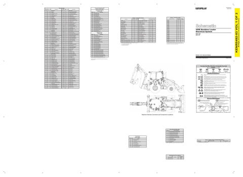
450E Backhoe Loader Electrical System RBA1-209 EBL1-UP
The connectors shown in this chart are for harness to harness connectors. Connectors that join a harness to a component are generally located at or near the component. See the Component Location Chart.
Volume 1 of 2: Cab and Chassis
¹ The CID is a diagnostic code that indicates which circuit is faulty.
© 2012 Caterpillar, All Rights Reserved
Printed in U.S.A.
² The MID is a diagnostic code that indicates which electronic control module diagnosed the fault.
Harness And Wire Electrical Schematic Symbols Symbols
T
Pressure Symbol
12 17
Temperature Symbol
16
Level Symbol
Circuit Breaker Symbol
Flow Symbol
Symbols and Definitions Fuse: A component in an electrical circuit that will open the circuit if too much current flows through it. Switch (Normally Open): A switch that will close at a specified point (temp, press, etc.). The circle indicates that the component has screw terminals and a wire can be disconnected from it.
22 21
20 14
B
4
Stabilizer Down Solenoid (LH)
T970
Schematic Location
Connector Number
1
Switch (Normally Closed): A switch that will open at a specified point (temp, press, etc.). No circle indicates that the wire cannot be disconnected from the component.
A
5
6
7
Ground (Wired): This indicates that the component is connected to a grounded wire. The grounded wire is fastened to the machine.
19
C
3
Ground (Case): This indicates that the component does not have a wire connected to ground. It is grounded by being fastened to the machine.
9
2
11
18
13
8
Reed Switch: A switch whose contacts are controlled by a magnet. A magnet closes the contacts of a normally open reed switch; it opens the contacts of a normally closed reed switch.
10
Sender: A component that is used with a temperature or pressure gauge. The sender measures the temperature or pressure. Its resistance changes to give an indication to the gauge of the temperature or pressure.
T
Relay (Magnetic Switch): A relay is an electrical component that is activated by electricity. It has a coil that makes an electromagnet when current flows through it. The electromagnet can open or close the switch part of the relay. Solenoid: A solenoid is an electrical component that is activated by electricity. It has a coil that makes an electromagnet when current flows through it. The electromagnet can open or close a valve or move a piece of metal that can do work. Magnetic Latch Solenoid: A magnetic latch solenoid is an electrical component that is activated by electricity and held latched by a permanent magnet. It has two coils (latch and unlatch) that make electromagnet when current flows through them. It also has an internal switch that places the latch coil circuit open at the time the coil latches.
Harness and Wire Symbols
6 22
21 15
20 16
2
7
C-C4 130-6795
19 14
3
Harness Connector Serialization Code: The "C" stands for "Connector" and the number indicates which connector in the harness. (C1, C2, C3, .....)
1
B
C
Socket
L-C12 3E-5179
AG-C4 111-7898
5A
Receptacle Pin or Socket Number
Single Wire Connector
10
Part Number For Connector Recepticle
1
325-AG135 PK-14 Pin
9
8
Part Number for Connector Plug
AG-C3 130-6795
12
4
Harness Identification Letter(s): (A, B, C, ..., AA, AB, AC, ...)
5
18
13
Sure-Seal connector: Typical representation of a Sure-Seal connector. The plug and receptacle contain both pins and sockets.
1 2
Wire, Cable, or Harness Assembly Identification: Includes Harness Identification Letters and Harness Connector Serialization Codes
A 17
Deutsch connector: Typical representation of a Deutsch connector. The plug contains all sockets and the receptacle contains all pins.
1 2
9X-1123
Component Part Number
Plug
11
2
Harness identification code: This example indicates wire 135 in harness "AG".
Fuse (5 Amps)
Ground Connection
200-L32 BK-14 Circuit Identification Number
Wire Color
Wire Gauge
Machine Harness Connector and Component Locations
Failure Mode Identifiers (FMI)¹ FMI No. 00
Failure Description Data valid but above normal operational range.
01
Data valid but below normal operational range.
02
Data erratic, intermittent, or incorrect.
03
Voltage above normal or shorted high.
04
Voltage below normal or shorted low.
05
Current below normal or open circuit.
06
Current above normal or grounded circuit.
Event Codes Engine Control
07
Mechanical system not responding properly.
08
Abnormal frequency, pulse width, or period.
Condition
09
Abnormal update.
10
Abnormal rate of change.
Event Code E172
High Air Filter Restriction
E194
High Exhaust Temperature
E360
Low Oil Pressure
E361
High Engine Coolant Temperature
E362
Engine Overspeed
E396
High Fuel Rail Pressure
E398
Low Fuel Rail Pressure
E539
High Intake Manifold Air Temperature
E1044
High Intake Manifold Pressure
E1045
Low Intake Manifold Pressure
11
Failure mode not identifiable.
12
Bad device or component.
13
Out of calibration.
Volume 1 - Resistor, Sender and Solenoid Specifications Part No.
Reserved 14-31 ¹The FMI is a diagnostic code that indicates what type of failure has occurred.
Related Electrical Service Manuals Title Electric Starting Motor:
Form Number 143-0539
SENR3828
Engine Control System:
KENR6949
Machine Control System:
KENR5494
134-2540
Component Description Resistor:
CAN
¹ At room temperature unless otherwise noted.
Resistance (Ohms)¹ 120
(Dimensions: 48 inches x 35 inches)
Description
36 Page,
Wire Color
KENR5492-03 VOL 1 OF 2
Wire Number
KENR5492-03 March 2012
Component Identifiers (CID¹) Module Identifier (MID²)