CONN 18
109
104
CONN 16
113
Connector Location Schematic Location
Connector Number CONN 1
J-15
CONN 2
I-15
CONN 3
H-14
CONN 4
G-14, G-15
CONN 5
I-15
CONN 6
G-15
CONN 7
E-14
114
11
CONN 37
95
FRONT CONSOLE
CONN 9
CONN 12
CONN 10
D-16
1
Solenoid - Hoe Aux Valve 1-1
G-16
66
Alarm As - Backup
I-16
2
Solenoid - Hoe Aux Valve 1-2
F-16
67
Alternator
D-4
3
Solenoid - Hoe Aux Valve 2-1
G-16
68
Battery
D-6
4
Solenoid - Hoe Aux Valve 2-2
G-16
69
F-5
70
Blower Gp - Cab (Heater)
C-12
5
Solenoid - Hyd Torque Limit
Compressor Gp - Refrigerant
H-3
6
Solenoid - Implement Lockout
H-16
71
Control Gp - Engine ECM
E-2
7
Solenoid - Pattern Changer 1
I-16
72
Control Gp - Joystick (LH)
H-16
8
Solenoid - Pattern Changer 2
I-16
73
Control Gp - Joystick (RH)
G-16
9
Solenoid - Reverse
E-5
74
Control Gp - Machine ECM
J-10
10
Solenoid - RTD Loader
H-6
75
Control Gp - Transmission (Fwd, Neu, Rev)
H-10
11
Solenoid - Wastegate Actuator
D-3
76 77
Electronics Gp - Communication (PL 300)
J-6
12
Suppressor - Arc
J-3
Flasher As - (12-Volt)
I-2
13
Suppressor - Arc (Front Work)
J-11
78
Glow Plugs
C-4
14
Suppressor - Arc (HVAC)
G-3
79
Ground - Control
D-7
15
Suppressor - Arc (Hyd Torque Limit)
F-5
80
Ground - Engine
G-7
16
Suppressor - Arc (Implement Enable)
H-16
81
Ground - Lower Cab
D-7
17
Suppressor - Arc (Pattern Changer)
I-16
82
Ground - Upper Cab
B-16
18
Suppressor - Arc (Rear Work)
I-11
83 84
Ground - Upper Cab
F-16
19
Suppressor - Arc (Ride Control)
H-6
Horn - Forward
G-5
20
Suppressor - Arc (RTD)
H-6
85
Injectors
E-4
21
Suppressor - Arc (XMSN Diode Block)
G-11
86
E-14
Module Gp - Display
D-16
22
Suspension Gp - Seat
D-7
87
B-13, C-13
Motor Gp - Front Washer
G-5
23
Switch - Air Filter
F-5
88
Motor Gp - Rear Washer
G-5
24
Switch - Temp (HVAC) (Air, Heater Select)
Motor Gp - Starter
D-5
25
Switch As - Battery Disconnect
CONN 10
B-13
CONN 11
C-12, C-13
CONN 12
D-13
Motor Gp - Window Wiper - (Front)
F-15
26
CONN 13
C-13
Motor Gp - Window Wiper (Rear)
F-16
27
CONN 14
C-13
Panel Gp - Fuse (Includes Relay)
E-1
CONN 15
C-13
Radio - Product Link
CONN 16
H-11
Relay As - (12-Volt) (All Wheel Drive)
CONN 17
G-11
Relay As - (12-Volt) (Backup Alarm)
CONN 18
G-11
Relay As - (12-Volt) (High Speed)
CONN 19
F-11
C-12
89
E-7
90
Switch As - Engine Shutdown
D-5
91
Switch As - Foot (Differential Lock on, off)
I-11
92
28
Switch As - Limit (Service Brake, LH)
I-11
93
J-8
29
Switch As - Limit (Service Brake, RH)
I-11
94
F-1
30
Switch As - Multifunction (HD Light, Turn, Wiper)
D-11
95
H-1
31
Switch As - Parking Brake
E-13
96
C-11
32
Switch As - Pressure (Hyd Oil Filter Bypass)
E-5
97
Relay As - (12-Volt) (Horn)
H-1
33
Switch As - Pressure (Refrigerant)
H-3
98
Relay As - (12-Volt) (Implement Disable)
G-1
34
Switch As - Pressure (Ride Control)
H-6
99
Relay As - (12-Volt) (Position Lamp)
H-1
35
Switch As - Pressure (Service Brake)
H-16
100
Relay As - (12-Volt) (Ride Control)
F-1
36
Switch As - Return to Dig
I-6
101
Relay As - (12-Volt) (Start)
D-4
37
Switch As - Rocker (Air Cond, Htr Select)
D-12
102
Relay As - (12-Volt) (Torque Limiter)
I-2
38
Switch As - Rocker (All Wheel Drive)
F-10
103
Relay As - Timer
I-16
39
Switch As - Rocker (Autoshift, Standard Shift)
H-10
104
CONN 20
I-7
CONN 21
I-7
CONN 22
E-7, F-7
CONN 23
E-7
CONN 24
C-7, J-5
CONN 25
E-7, F-7
Relay Gp - (12-Volt) (Power Distribution)
J-1
40
Switch As - Rocker (Auxiliary Hydraulic Fan)
E-15
105
CONN 26
H-7
Relay Gp - (12-Volt) (Power, 1)
J-2
41
Switch As - Rocker (Blower Fan Speed)
C-12
106
CONN 27
H-7
Relay Gp - (12-Volt) (Power, 2)
J-2
42
Switch As - Rocker (Floodlight, Front)
D-15
107
CONN 28
J-2
Relay Gp - Power (Engine)
C-5
43
Switch As - Rocker (Floodlight, Rear)
D-15
108
CONN 29
J-7
Resistor As - Connection (3-Pin)
I-7
44
Switch As - Rocker (Hazard Warning Lights)
E-11
109
CONN 30
J-7
Resistor As - Connection (3-Pin)
H-15
45
Switch As - Rocker (Horn)
F-10
110
CONN 31
I-6
Resistor As - Excitation
D-4
46
Switch As - Rocker (Hydraulic Lockout)
E-15
111
CONN 32
G-5
Resistor As - Motor Speed
B-12
47
Switch As - Rocker (Mode Select)
J-11
112
CONN 33
E-5, J-5
Sender - Coolant Temperature
F-5
48
Switch As - Rocker (Ride Control)
F-10
113
CONN 34
E-5, I-5
Sender - Fuel Level
G-5
49
Switch As - Rocker (Transmission Neutral Lock)
G-10
114
CONN 35
E-5, J-5
Sender As - Temperature (Transmission)
F-5
50
Switch As - Rocker (Warning Beacon)
D-15
115
CONN 36
E-5, J-5
Sensor - Pressure (Water Separator)
G-5
51
Switch As - Rocker (Wiper, Washer, Rear)
C-15
116
Sensor Gp - Coolant Temperature
D-3
52
Switch As - Start (Key)
C-16
117
Sensor Gp - Crankshaft Speed
D-3
53
Switch Gp - Push Button (Neutralizer)
I-7
118
Sensor Gp - Fuel Rail Pressure
E-4
54
Valve Gp - Pilot (Stabilizer)
J-16
119 120
CONN 19
94
Alarm - Action
CONN 9
UNDER FRONT CONSOLE
CONN 8 CONN 14
93
Machine Location
CONN 8
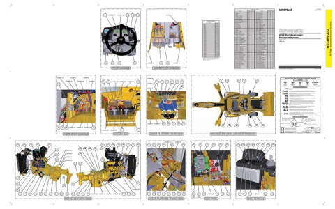
CONN 37 I-11 The connectors shown in this chart are for harness to harness connectors. Connectors that join a harness to a component are generally located at or near the component. See the Component Location Chart.
103
Schematic Location
Component
Sensor Gp - Hyd Oil Temperature
D-5
55
Valve Gp - Solenoid (12-Volt) (Accum)
H-6
Sensor Gp - Intake Manifold Pressure
F-4
56
Valve Gp - Solenoid (All Wheel Drive)
J-3
121
Sensor Gp - Intake Manifold Temperature
D-3
57
Valve Gp - Solenoid (Diff Lock)
J-3
122 123
Sensor Gp - Oil Pressure
E-4
58
Valve Gp - Solenoid (Forward High)
I-3
Sensor Gp - Position (Rotary)
F-5
59
Valve Gp - Solenoid (Forward Low)
I-3
124
Sensor Gp - Pump Cam Speed
D-3
60
Valve Gp - Solenoid (Reverse)
I-3
125
Sensor Gp - Speed (Transmission)
F-5
61
Valve Gp - Solenoid (Speed Clutch 1)
J-3
126
Solenoid - All Wheel Drive
E-5
62
Valve Gp - Solenoid (Speed Clutch 2)
J-3
127
Solenoid - Diff Lock
E-5
63
Valve Gp - Solenoid (Speed Clutch 3)
J-3
128
Solenoid - Forward
E-5
64
Valve Gp - Solenoid (Ride Control, Switch)
H-6
129
Solenoid - Fuel Pump
D-3
65
450E Backhoe Loader Electrical System RBA210-UP LYR1-UP
© 2012 Caterpillar, All Rights Reserved
Harness And Wire Electrical Schematic Symbols
CONN 6 CONN 7
29
44
CONN 30 CONN 20
CONN 31
12
81
82
69
68
73
9
72
112
92
49
Symbols
26
CONN 4
47
Printed in U.S.A.
T
Pressure Symbol
Temperature Symbol
66
Level Symbol
Flow Symbol
Circuit Breaker Symbol
Symbols and Definitions
CONN 3
Fuse: A component in an electrical circuit that will open the circuit if too much current flows through it. Switch (Normally Open): A switch that will close at a specified point (temp, press, etc.). The circle indicates that the component has screw terminals and a wire can be disconnected from it. Switch (Normally Closed): A switch that will open at a specified point (temp, press, etc.). No circle indicates that the wire cannot be disconnected from the component. Ground (Wired): This indicates that the component is connected to a grounded wire. The grounded wire is fastened to the machine. Ground (Case): This indicates that the component does not have a wire connected to ground. It is grounded by being fastened to the machine. Reed Switch: A switch whose contacts are controlled by a magnet. A magnet closes the contacts of a normally open reed switch; it opens the contacts of a normally closed reed switch. Sender: A component that is used with a temperature or pressure gauge. The sender measures the temperature or pressure. Its resistance changes to give an indication to the gauge of the temperature or pressure.
T
Relay (Magnetic Switch): A relay is an electrical component that is activated by electricity. It has a coil that makes an electromagnet when current flows through it. The electromagnet can open or close the switch part of the relay. Solenoid: A solenoid is an electrical component that is activated by electricity. It has a coil that makes an electromagnet when current flows through it. The electromagnet can open or close a valve or move a piece of metal that can do work. Magnetic Latch Solenoid: A magnetic latch solenoid is an electrical component that is activated by electricity and held latched by a permanent magnet. It has two coils (latch and unlatch) that make electromagnet when current flows through them. It also has an internal switch that places the latch coil circuit open at the time the coil latches.
Harness and Wire Symbols Wire, Cable, or Harness Assembly Identification: Includes Harness Identification Letters and Harness Connector Serialization Codes (see sample).
Harness Identification Letter(s): (A, B, C, ..., AA, AB, AC, ...)
L-C12 3E-5179
AG-C4 111-7898
CONN 5 CONN 2
100
45
71
67
2
38
13
89
CONN 15 CONN 11 CONN 13
4
CONN 21
54
21
24
57 128
14
46
18
19
101
Plug
64
23
91
37
48
UNDER PLATFORM - REAR VIEW
6
79
20
15
17
78
83
10
59
84
120
MACHINE TOP VIEW - CAB ROOF REMOVED
CONN 27 85
118
35
33
87
36
30
NOT SHOWN
NOT SHOWN
31
28
41
32
115
117
107
108
1
22
116
105
50
CONN 23 CONN 25
76
125
CONN 22 74
43
CONN 24 55
97
56
65
3
70 122
CONN 32
60 58
7
53
51
63
62
123
49
127
80
124
121
126
61
CONN 33
ENGINE VIEW WITH XMSN
CONN 34 CONN 35 CONN 36
16
25
98
Receptacle Pin or Socket Number
1 2
Deutsch connector: Typical representation of a Deutsch connector. The plug contains all sockets and the receptacle contains all pins.
1 2
Sure-Seal connector: Typical representation of a Sure-Seal connector. The plug and receptacle contain both pins and sockets.
5A Fuse (5 Amps)
9X-1123
Component Part Number
325-AG135 PK-14
CONN 26 88
96
90
BATTERY BOX
UNDER RIGHT CONSOLE
52
8
Part Number: for Connector Receptacle
2
5 CONN 29
1
Part Number: for Connector Plug
27
L-C12 3E-5179
Harness Connector Serialization Code: The "C" stands for "Connector" and the number indicates which connector in the harness (C1, C2, C3, ...).
129
99
75
UNDER PLATFORM - FRONT VIEW
34
CONN 28
77
FUSE PANEL
42
40
111
102
106
CONN 1
RIGHT CONSOLE
39
119
Harness identification code: This example indicates wire group 325, wire 135 in harness "AG".
Wire Gauge Wire Color
42 Page,
CONN 17
86
Machine Location
UENR0272
Schematic Location
Component
(Dimensions: 56 inches x 35 inches)
UENR0272 November 2012
Component Location