Wire Description
50(1)
41
8 VDC Supply Electrical System Voltage
191
Transmission Output Speed Sensor
247
SAE J1939 Data Link
262
5 VDC Supply
367
Ride Control Switch
50(1)
368
Transmission Auto/Manual Switch
434
Hydraulic Pilot Oil Pressure Sensor
490
Implement Lockout Switch
590
Engine Control Module
153
Warning Level 1
3
3
Description High Voltage Level 1 Event
High Voltage Level 3 Event
High speed directional shift
Activation 1. Start-up delay timer is expired (30 sec) and 2. Engine speed is greater than 800 RPM and 3. System Voltage is greater than 14.8 VDC to activate (less than 14.5 VDC to deactivate) and 4. Debounce status is TRUE. 1. System Voltage is greater than 16 VDC to activate (less than 15.8 VDC to deactivate) and 2. Debounce status is TRUE. 1. Ground speed is greater than 16 km/h (10 mph) and 2. A shift in direction is requested by the operator. A “Shift in Direction” is defined as: 1. Shift from Fwd to Rev
Component Location Schematic Location
Machine Location
Alarm - Accugrade
A-15
B
Antenna
F-13
Block - Diode (XMSN) FNR - Shift Handle
Component
871
“Accugrade” Inclination Front Facing Position Seat Switch
1037
Display Module
1251
Application Location Code
1401
Transmission Solenoid 1
1402
Transmission Solenoid 2
1403
Transmission Solenoid 3
1404
627(1)
797(2)
Transmission Solenoid 4 Transmission Solenoid 5
1406
Transmission Solenoid 6
1482
10 Volt Sensor DC Power Supply Implement Front Auxiliary Quick Coupler Flow Switch
797(1)
1834
Ignition Key Switch
1956
Implement Hoe Bucket Position Sensor
1957
Implement Hoe Stick Position Sensor
1958
Implement Hoe Estick Position Sensor
1959
Boom Cylinder Position
1960
MSS_trm Communication Diag
2108
Dev -- Hoe Swing Sensor
2236
Hoe Auxiliary Valve #1 Port A Solenoid
2237
Hoe Auxiliary Valve #1 Port B Solenoid
2242
Loader Auxiliary Valve Port A Solenoid
2243
Loader Auxiliary Valve Port B Solenoid
2244
Hoe Auxiliary Valve #2 Port A Solenoid
2245
Hoe Auxiliary Valve #2 Port B Solenoid Loader Joystick Thumbwheel Position Sensor
2529
Hoe Left Joystick Thumbwheel Position Sensor
2531
Hoe Right Joystick Thumbwheel Position Sensor
2735
Implement Front Auxiliary Continous flow switch
2736
Hoe Auxiliary Continuous Flow Switch
2977
Low Idle Switch Implement Valve Load Sense Pressure Sensor
3084
2
Machine Driven with Parking Brake ON
The engine coolant temperature is greater than 113 °C (235 °F) for 3 seconds 1. The ground speed is greater than 1 km/h (0.6 mph) in forward or reverse and
1 3
Brake Boost Low Pressure Level 1 Event Brake Boost Low Pressure Level 3 Event
1. Fluid level / pressure for the brake is low and 2. Engine speed is less than 800 RPM. 1. Fluid level / pressure for the brake is low and 2. Engine speed is greater than 800 RPM.
861(1)
1
Machine Synchronize clock Manual Alignment
The SYNC Clock requires Manual Adjustment.
875(1)
1
Low Voltage Level 1 Event
1. Start-up delay timer is expired (30 sec) and 2. Engine speed less than 400 RPM and 3. System Voltage is 12.3 -12.5 VDC and 4. Debounce status is TRUE (8 minute debounce on bench test). OR 1. Start-up delay timer is expired (30 sec) and 2. Engine speed greater than 1300 RPM and 3. System voltage is 12.4 -13 VDC and 4. Debounce status is TRUE.
E-9
A
Suppressor - Front
F-8 F-8
B
Switch - Autoshift Manual
B-14 C-9
Connector Location
101
RD
Bat (+) (Not Application Specific)
945
BR
103
RD
PRM Module #1
973
BR
105 110 111
CST Autoshift- Auto/Manual Switch 2
RD RD RD
Key Switch Flasher Rear Horn Relay
975 976 977
WH OR YL
CST Autoshift- Sol Return Ride Control Solenoid #1 CST Autoshift- Auto/Manual Switch #1
112
PU
PRM Module #2
994
GY
Oil Pressure (Filtered)
115
RD
ACC Power Port
995
BU
Coolant Temperature
996
GN
Engine/Speed Timing (Crankshaft) Throttle Switch 1
875(1)
875(1)
878(1)
2
3
2
Low Voltage Level 2 Event
Low Voltage Level 3 Event
High Hydraulic Oil Temperature Event
Description
Control Circuits (Continued) CAT Data Link -
Schematic Location
Machine Location
116
BR
Rear Flood Lamp
117
YL
Rear Flood Lamp (ATCH)
A755
PK
CONN 1
H-13
1
118
GY
Front Wiper
A756
BU
Throttle Switch 2
B
CONN 2
H-13
1
15
CONN 3
G -13
1
119 121
PK YL
Rear Wiper Backup Alarm To Lamp
A757 A758
GY BR
Throttle Switch 3 Throttle Switch 4
15
CONN 4
E-13
2
122
BU
Heater/AC Switch
C720
BU
Interlock Relay
B
CONN 5
E-13
2
123
WH
Quick Coupler
C743
PK
Parking Brake
A
CONN 6
A-11
3
124
GN
A/C Compressor
C949
YL
Brake Pressure Sensor
A-11
3
126
RD
Grade Check ECM
C967
BU
Inlet Air Temperature
Connector Number
B-9 B-14
A
Switch - AWD
H -9
A
CONN 7
B
Switch - Beacon
C-14
B
CONN 8
C-11
3
127
OR
Laser Grade Check
E455
BR
Hydraulic Oil Filter Switch
Indicator - Lamp (LH)
B-9
A
Switch - Brake (LH)
CONN 9
C-11
3
A-14
B
Switch - Brake (RH)
E-9 E-9
A
Indicator - Wait to Start
A
CONN 10
B -11
3
133 136
OR GN
PHS Solenoid Differential Lock Relay
E540 E543
PK WH
Aux Hydraulic Interlock Aux Hyd. Return Solenoid (Close)
Joystick - Loader
E-3
B
Switch - Control Flow 7-8
D-14
B
CONN 11
C-11
3
D-11
3
143 144
BR GN
Differential Lock/AWS Beacon
E544 E701
GN PK
Aux Hyd. Return Solenoid (Open) Auto Ride Control Switch
Indicator - Assembly (RH)
Machine - ECM
I -7
10
Switch - Control Pattern
I-9
A
CONN 12
Meter - Service
I-9 H-2
A
Switch - Differential Lock
CONN 13
D-11
3
146
GY
PRM Module #1
E750
PU
Body Position Sensor (Load Switch)
B
Switch - Front Work Lamp
F-8 D-14
16
Module - PRM 1
B
CONN 14
D-9
4
150
OR
Batt (+)
E803
YL
Right Ind Steer Solenoid
Module - PRM 2
H-2
B
Switch - Hazard
C-9
A
CONN 15
D-9
4
157
YL
Front Flood Lamp (ATCH)
E804
BU
Left Ind Steer Solenoid
I -4
5
158
BR
Front Flood Lamp
E885
OR
Bucket Dump Exchange
H-1
B
Switch - Horn (Front Console)
G -9
A
CONN 16
Module - PRM (HVAC)
H-1
B
Switch - Horn (Steering Column)
B -8
A
CONN 17
I-4
5
180
GN
Operator Seat
E900
WH
ECPC Trans Output Speed +
Motor - Front Wiper
F-13
11
Switch - Implement Lockout
D-14
B
CONN 18
I-4
5
181
GY
Engine Speed Control (+)
E901
GN
ECPC Trans Output Speed -
Motor - Rear Wiper
F-15
12
Switch - Key
A-15
B
CONN 19
H-4
5
182
PU
H-4
7
Module - PRM (Engine)
Engine Underspeed Control
E917
WH
Implement Lockout Switch To Ground (N.O.)
Ground Circuits
E918
GN
Implement Lockout Switch To Ground (N.C.)
Motor - Seat Group
F -3
13
Switch - Neutral Loader Handle
F-4
B
CONN 20
Power - Port #1
D-12 I-9
B
Switch - Neutral XMSN Handle
F-4
B
CONN 21
G -4
7
200
BK
Main Chassis
E965
BU
Engine Speed/Timing Sensor (Camshaft)
14
Switch - Park Brake
C-12
B
CONN 22
G-4
7
202
BK
XMSN Control
E991
GY
Implement Lock out Switch
Rela y - AWD Brake
C-1
C
Switch - Rear Wiper
A-14
B
CONN 23
G-4
7
207
BK
Start Relay
F420
GN
Warning Lamp
Relay - Backup Alarm
C
Switch - Rear Work Lamp
C-14
B
CONN 24
F -4
3
F702
GN
Throttle Position
Relay - Horn
F-1 F-1
C
Switch - Ride Control
G-9
A
CONN 25
F -4
5
304
WH
Starter Relay No. 1 Output
F711
GN
CAN Link +
Relay - Implement Enable
D-1
C
Switch - Stalk
B-9
A
CONN 26
E-4
5
306
GN
Starter Relay Coil Or Key Switch
F712
GY
CAN Link -
Relay - Position Lamp
F-1
C
Switch - XMSN Lock
H-9
A
Active Ride Control Switch (N.C.)
Power - Port #2
Relay - Ride Control
C-1
B
Relay - Start
G-2
B
Relay - Torque Limiter
G-2
B
Timer - Stabilizer
I-13 H-15
Valve - Stabilizer
17 17
Basic Machine Circuits
CONN 27
E-4
5
307
OR
Key Switch To Shifter
F738
WH
CONN 28
D-4
5
308
BK
Keyswitch Power (+)
F739
GN
Active Ride Control Switch (N.O.)
CONN 29
D-4
5
309
GY
Alternator Regulator Terminal
F748
WH
Ride Control Switch
CONN 30
D-4
5
310
PU
Start Aid Switch To Start Aid Solenoid
G423
PK
Hydraulic Filter Bypass
CONN 31
C-4
5
OR BR
Horn Relay Coil To Switch Backup Alarm Lamp Travel Alarm
G750 G755
BU GY
XMSN Forward Switch To Ground XMSN Reverse Switch To Ground Pilot Cutout Solenoid
Machine locations are repeated for components located close together.
CONN 32
I -2
8
A = Located inside of operator dash.
CONN 50
F -9
4
322
GY
Warning Horn (Forward)
G962
OR
324
BU
Differential Lock Solenoid
H416
GN
Lamp Indicator
331
OR
Backup Alarm Relay Coil
H705
BR
Pump Relay
Relay To Glow Plugs
H707
YL
Impl Cont Pump Torque Solenoid
H730 H731
BR GY
Reverse Output - Shuttle Control Forward Output - Shuttle Control Side Shift Lock Solenoid
The connectors shown in this chart are for harness to harness connectors. Connectors that join a harness to a component are generally located at or near the component. See the Component Location Chart.
B = Located inside of right console.
1. Start-up delay timer is expired (30 sec) and 2. Engine is running and 3. Engine speed less than 1300 RPM and 4. System Voltage is 12.4 -13 VDC and 5. Debounce status is TRUE. OR 1. Start-up delay timer is expired (30 sec) and 2. Engine is running and 3. System voltage is 12 -12.3 VDC and 4. Debounce status is TRUE. 1. Start-up delay timer is expired (30 sec) and 2. Engine speed is greater than 800 RPM and 3. System Voltage is 11.5 or 11.8 VDC and 4. Debounce status is TRUE. 1. Hydraulic oil temperature is greater than 110 °C (230. °F) and 2. ON delay timer (3 min) is expired.
(1) logged
AESC Enable Selection Switch
384
BU
A347
GN
403
GN
Alternator (R) Terminal
H771
BR
404
YL
Opr Mon Hydraulic Oil Temperature
H783
GN
AESC Control Indicator Lamp
405 420
GY OR
Opr Mon Oil Pressure (Low) Opr Mon Fuel Filter/Low Accum Pressure
H901 H902
OR YL
LVDT Signal - Boom 1 LVDT Signal - Bucket
432
PK
Opr Mon Brake Pressure (Oil)
H903
PK
LVDT Signal - EStick
439
YL
Water in Fuel Indicator
H904
GY
LVDT Signal - Swing
441
OR
Engine Coolant Temp Gage
H907
GN
LVDT Signal - Stick 2 Bypass
442
GY
Hydraulic Oil Temperature Sensor
J764
BR
Switch/Sensor Return #1
447
PK
Fuel Level Gage
J765
BU
Switch/Sensor Return #2
450 452
YL PU
Tach Sender (+) Torque Converter
J766 J878
PU YL
Switch/Sensor Return #3 Switch/Sensor Return #5
483
BR
Brake Fluid Level
J984
PK
Analog 1
E455 F420
BR GN
Hydraulic Oil Filter Warning Lamp (General)
K753 K754
OR PK
Power Mod Relay (+) Power Mod relay (-)
G423
PK
High Pressure Implement Filter - Rear
K973
PK
Hex Engine Speed Control 1
H416
GN
Lamp Indicator
K974
PU
Hex Engine Speed Control 2
Accessory Circuits
K975
WH
Hex Engine Speed Control 3
MSS Start Condition Indicator Monitoring Circuits
500
BR
Wiper - Front (Park)
L730
OR
Analog Sensor Return (+5V)
501
GN
Wiper - Front (Low)
L731
BR
Analog Sensor Return (+5V)
² The MID is a diagnostic code that indicates which electronic control module diagnosed the fault.
502
OR
Wiper - Front (Hi)
L740
BR
Analog Sensor Return (+5V)(VCM)
503 506
BR PU
Wiper - Rear (Park) Washer - Front
L998 L999
OR GN
Auxiliary Hydraulic Solenoid B Auxiliary Hydraulic Solenoid C Waste Gate Valve (+)
Failure Mode Identifiers (FMI) FMI
1
Failure Description
507
WH
Washer - Rear
M795
WH
PU
Radio Speaker - Left
M936
BR
Flow Control Switch
509
WH
Radio Speaker - Left (Commom)
M937
GN
Flow Control Prox Sw #1
BR
Radio Speaker - Right
M952
BU
LH Joystick
512
GN
Radio Speaker - Right (Common)
M965
GN
RH Joystick
513 515
OR GY
A/C Compressor/Refrigerant Pressure Sw. Blower Motor (HI)
M968 M969
BU YL
Coupler Switch Interconnect Coupler Switch Interconnect
516
GN
Blower Motor (Medium)
N756
PK
Alarm Horn Output
517
BU
Blower Motor (Low)
N939
GN
Ride Control Solenoid
518
OR
Hazard Flasher To Switch
N945
OR
AWD (Signal)
A/C Refrigerant High Pressure
N957
WH
A/C Switch To Thermostat Switch
GN WH
Turn Signal Switch To Flasher Four Wheel Drive Solenoid
PK
520
T
PK
RS-232 RXD - COMM #1
N959
PK
RS-232 RXD - COMM #3
N960 N963
OR OR
RS-232 TXD - COMM #1 RS-232 TXD - COMM #3
Data valid but above normal operating range
1
Data valid but below normal operating range
537 552
2
Data erratic, intermittent or incorrect
564
GY
Rear Wiper Interrupt Switch To Wiper Sw.
N970
YL
RS-232 DTR - COMM #1
568
GN
Parking Brake Warning Buzzer To Diodes
N973
BR
RS-232 DCD - COMM #1
569
PK
A/C Switch Jumper #2
N979
GN
RS-232 Signal Ground - COMM #1
578
BU
Auxiliary Washer
N981
GN
RS-232 Signal Ground - COMM #3
4
Voltage below normal or shorted low
5
Current below normal or open circuit
585
YL
Aux Hydtraulic - Open
N997
WH
PWM - Freq In #1
6
Current above normal or grounded circuit
7
Mechanical system not responding properly
586 597
BR PU
Aux Hydtraulic - Closed A/C High Press. Cutout Switch
P914 P920
GN BR
XMSN Forward Indicator EUI Secondary Engine Speed/Timing
A510
OR
A/C Low Press. Cutout Switch
P993
OR
Auxiliary Hydraulic Select
C506
WH
High Speed Relay
R762
GY
Control Pattern Switch
C510 E528
WH PU
A/C Compressor Relay Switch HVAC On/Off Switch To Blower Switch
R763 R912
BU OR
Control Pattern Switch Hydraulic Pedal Lock Solenoid
E529
YL
Blower Switch Jumper
R954
BK
Discrete Output 1
E540
PK
Aux Hydraulic Interlock
R955
GY
Discrete Output 2
E543
WH
Aux Hydraulic Return Solenoid - Close
R956
BU
Discrete Output 3
E544
GN
Aux Hydraulic Return Solenoid - Open
R956
BK
Discrete Output 3
Lighting Circuits
R957
GY
Discrete Output 4
Abnormal update rate
10
Abnormal rate of change
11
Failure mode not identifiable
12
Bad device or component
13
Out of calibration
9 11
12
15
Data valid but above normal operational range
603
PK
Rotary Beacon
R958
GN
Discrete Output 5
16
Data valid but above normal operational range
17
Data valid but below normal operational range
604 605
OR YL
Stop Lamp Turn Lamp - Left
R997 T901
OR YL
Analog Sensor Power (+5v) MSS Exciter Coil In
18
Data valid but below normal operational range
19
Received network data in error
606 607
GY PK
Turn Lamp - Right Flood Lamp - Front
T902 T904
PK BU
MSS Exciter Coil Out RH Stabilizer Up - Switch To Solenoid
608
GN
Flood Lamp - Rear
T907
GN
LH Stabilizer Down - Switch To Solenoid
614 617
PU BR
Park/Tail/Dash/Lamp Tail/Position Lamp - Left (Road Package)
T969 T970
YL GY
Aux Circuit 1 Stick Extend Solenoid (+)
618 620
YL WH
Tail/Position Lamp - Right (Road Package) Flood Lamp - Front
T971 T972
OR GN
Aux Circuit 3 Stick Extend Solenoid (+)
630
GY
Flood Lamp Rear (ATCH)
T993
BR
Analog Sensor Return
668
BU
Backlight Relay
T997
OR
Analog Sensor Power (+5v)
Control Circuits
X731
BU
Boost Pressure to Controller
4 3 17
C
1
B 14 8
2
15
13 10 7 6
16
5
OR
XMSN Brake Switch LH
X740
BU
Seat Forward to Controller
YL
XMSN Neutral Lock Switch
X750
OR
Fwd/Rev Solenoid Return From Controller
720 751
PU GN
XMSN Brake Switch RH XMSN Shift Solenoid (No. 1 OR 3)
X800 X920
OR BR
+8V Sensor Power Injector 1 Hi Side
752
YL
XMSN Shift Solenoid (No. 2 - Reverse)
X921
PK
Injector 2 Hi Side
754
BU
XMSN Shift Sol (No. 3 Or No. 1 - Forward)
X922
WH
Injector 3 Hi Side
762
YL
Bucket Positioner Solenoid Switch
X923
OR
Injector 4 Hi Side
766
GN
XMSN Disconnect Solenoid
X926
GY
Injector 1 Return
YL
AETA Solenoid - Left
X927
YL
Injector 2 Return
WH
Coupler Engage Solenoid
X928
GN
Injector 3 Return
Ground (Wired): This indicates that the component is connected to a grounded wire. The grounded wire is fastened to the machine.
Sender: A component that is used with a temperature or pressure gauge. The sender measures the temperature or pressure. Its resistance changes to give an indication to the gauge of the temperature or pressure. Relay (Magnetic Switch): A relay is an electrical component that is activated by electricity. It has a coil that makes an electromagnet when current flows through it. The electromagnet can open or close the switch part of the relay.
Magnetic Latch Solenoid: A magnetic latch solenoid is an electrical component that is activated by electricity and held latched by a permanent magnet. It has two coils (latch and unlatch) that make electromagnet when current flows through them. It also has an internal switch that places the latch coil circuit open at the time the coil latches.
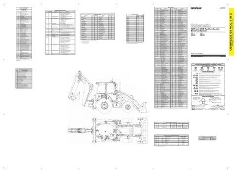
Harness and Wire Symbols Wire, Cable, or Harness Assembly Identification: Includes Harness Identification Letters and Harness Connector Serialization Codes (see sample).
Harness Identification Letter(s): (A, B, C, ..., AA, AB, AC, ...)
L-C12 3E-5179
AG-C4 111-7898
799
WH
Sensor Power
X929
BU
Injector 4 Return
852
GN
Continuious Flow Sensor (signal)
Y794
OR
Expanded CAN Data Link +
892
BR
Cat Data Link (-)
Y795
GN
Expanded CAN Data Link -
893
GN
Cat Data LInk (+)
Y946
BU
Fuel Rail Pressure
900
PU
XMSN Shift Sol No. 5 Or 4
Y947
BR
Analog Sensor Return
902
BR
XMSN Shift Sol No. 7
Y948
BR
Analog Sensor Return
903
GY
XMSN Shift Sol No. 8
Y950
YL
Fuel Pump Solenoid (+)
911
YL
AWD Mode Relay Switch Jumper
Y951
PU
Fuel Pump Solenoid (-)
944
OR
CAT Data Link +
L-C12 3E-5179
Harness Connector Serialization Code: The "C" stands for "Connector" and the number indicates which connector in the harness (C1, C2, C3, ...).
1
Part Number: for Connector Plug
Part Number: for Connector Receptacle
2 Plug
Receptacle Pin or Socket Number
1 2
Deutsch connector: Typical representation of a Deutsch connector. The plug contains all sockets and the receptacle contains all pins.
1 2
Sure-Seal connector: Typical representation of a Sure-Seal connector. The plug and receptacle contain both pins and sockets.
5A Fuse (5 Amps)
Harness identification code: This example indicates wire group 325, wire 135 in harness "AG".
Off Machine Switch Specification Part No. 16
Function
Actuate
Deactuate
Contact Position
207 kPa (30 psi)
Normally Open
134-0404
Hydraulic Bypass Oil Filter
276 ± 27.5 kPa MAX (40 ± 4 psi)
3E-7675
Boosted Brake Pressure
2550 kPa MAX (369.8 psi)
1800 ± 175 kPa (261 ± 25.3 psi)
Normally Closed
304-5696
Ride Control Pressure
3500 kPa MAX (507.6 psi)
3137 ± 175 kPa (455.0 ± 25.4 psi)
A-C, Normally Closed A-B, Normally Open
11
10 1 13
4
17
A
7
C 3
9
6
B 2
15 5
8
Resistor, Sender and Solenoid Specifications Part No.
Component Description
244-3106
Sender:
238-9397
Resistor:
4W-9972
Sender:
9X-1123
Component Part Number
325-AG135 PK-14
14
12
Switch (Normally Closed): A switch that will open at a specified point (temp, press, etc.). No circle indicates that the wire cannot be disconnected from the component.
Solenoid: A solenoid is an electrical component that is activated by electricity. It has a coil that makes an electromagnet when current flows through it. The electromagnet can open or close a valve or move a piece of metal that can do work.
708
779
Switch (Normally Open): A switch that will close at a specified point (temp, press, etc.). The circle indicates that the component has screw terminals and a wire can be disconnected from it.
T
702
774
Circuit Breaker Symbol
Reed Switch: A switch whose contacts are controlled by a magnet. A magnet closes the contacts of a normally open reed switch; it opens the contacts of a normally closed reed switch.
Special Instruction
A
Flow Symbol
Ground (Case): This indicates that the component does not have a wire connected to ground. It is grounded by being fastened to the machine.
14
¹The FMI is a diagnostic code that indicates what type of failure has occurred.
Level Symbol
Fuse: A component in an electrical circuit that will open the circuit if too much current flows through it.
Voltage above normal or shorted high
Abnormal frequency, pulse, or period
Temperature Symbol
Symbols and Definitions
3
9
Printed in U.S.A.
Symbols
Pressure Symbol
0
8
© 2012 Caterpillar, All Rights Reserved
Harness And Wire Electrical Schematic Symbols
511
519
430E: MXB1-UP SWC1-UP
Volume 1 of 2: Cab Wiring
¹ The CID is a diagnostic code that indicates which circuit is faulty.
508
420E and 430E Backhoe Loader Electrical System 420E: DJL1-UP DAN1-UP
320 321
C = Located around of fuse block.
2530
2997
High Engine Coolant Temperature
The engine oil pressure is low enough to activate the engine oil pressure switch for 3 seconds and the engine is not running.
2. The Parking Brake switch is closed for 1 second.
1405
1529
Low Engine Oil Pressure
361
Alternator R-Terminal Signal
1326
360
Suppressor - Arc
A-14
The air filter is restricted.
1009
A
Indicator - AESC
Neutralizer Switch
“FNR” Lever Diagnostics
A
E-9
D-8 I-2
Switch - AESC
629
702
Shifter - Autoshift
Suppressor - Rear
Indicator - Deluxe
Hydraulic Oil Filter Bypass Event 1. Hydraulic oil temperature is greater than 42 °C (108 °F) (Temp Limit) or Hydraulic Oil Temp is unknown or Event is previously active and still in hysteresis( 39 °C (102.2 °F)) and 2. The switch for the hydraulic filter is ACTIVE.
9
B
3. Shift out of neutral
2
B
B
Steering / Transmission Lock Switch
282(1)
H-14
C-1
626
Air Inlet Restriction
Resistor - Terminal (#3)
Component
G-2
Hydraulic Oil Temperature Sensor
5 min
Machine Location
Fuse - Block
600
172
Schematic Location
Flasher
2. Shift from Rev to Fwd
Transmission Shift Lever
Wire Color
Description
UENR0236-06 September 2012
Coolant Temperature Excitation Converter Temperature
3E-8620
Solenoid:
RTD Loader Valve
134-2540
Resistor:
Terminating
212-3350
Solenoid:
Loader QC
251-3231
Sender:
Fuel Level (EST)
167-7801
Resistor:
Terminal (Atch)
¹ At room temperature unless otherwise noted.
Resistance (Ohms)¹ 54.4°C (130°F) - 560 to 716 110°C (230°F) - 72 to 82 120 ± 5% 54°C (130°F) - 560 to 716 110°C (230°F) - 72 to 82 21.8 ± 1 120±10% 3.2 ± 7% Empty - 240-250 Full - 28-33 390 ± 5%
Related Electrical Service Manuals Title Electric Starting Motor: Machine Troubleshooting:
Form Number 143-0539
SENR3828 KENR7663
Wire Gauge Wire Color
(Dimensions: 48 inches x 35 inches)
EID
168
668
Wire Color
Power Circuits
Event Codes for the Machine ECM
Component
CID
Wire Number
36 Page,
Machine ECM (MID No. 039)
Wire Number
UENR0236-06 VOL 1 of 2
Component Identifiers (CID¹) Module Identifier (MID²)