Wire Color
Wire Number
Description
Wire Color
Accessory Circuits Continued
Power Circuits 518
32
D 13 16
1 3
6
11 7
2
A/C Switch To Refrigerant Switch
Bat (+) (Not Application Specific)
102
RD
Head Lamp
521
YL
103
RD
Power Batt (+) - Unswitched
522
WH
A/C Clutch To Thermostat Switch
104
YL
Auxilary Circuit
537
GN
Turn Signal Switch To Flasher
105
RD
Key Switch
552
WH
Four Wheel Drive Solenoid
106
WH
Auxilary Circuit
564
GY
Rear Wiper Interrupt Switch To Wiper Sw.
111
YL
Rear Horn Relay
568
GN
Park Brake Warning Buzzer
PRM Module #1
569
PK
A/C Switch Jumper #2
112
PU
115
RD
ACC Power Port
578
BU
Auxiliary Washer
116
BR
Rear Flood Lamp
585
YL
Aux Hydraulic - Open
117
YL
Rear Flood Lamp (ATCH)
586
BR
Aux Hydraulic - Closed
118
GY
Front Wiper
590
GY
Intermittent Wiper
119
PK
Rear Wiper
C511
WH
Relay Power
122
BU
Heater/AC Switch
C568
WH
Blower Motor
123
WH
Quick Coupler
E528
PU
HVAC On/Off Switch To Blower Switch
E529
YL
Blower Switch Jumper
124
GN
A/C Compressor
125
OR
Product Link
126
PK
Laser Grade Check
601
GY
Dash Lamp (Hi)
133
OR
Advisory Display
603
PK
Rotary Beacon
143
BR
Ride Control Relay
604
OR
Stop Lamp
144
GN
Beacon
605
YL
Turn Lamp - Left
146
GY
PRM Module #1
606
GY
Turn Lamp - Right
157
YL
Front Flood Lamp (ATCH)
607
PK
Flood Lamp - Front Flood Lamp - Rear
Lighting Circuits
158
BR
Front Flood Lamp
608
GN
159
BU
Aux Ckt
610
OR
Head Lamp - Basic
161
RD
Aux Ckt
611
PU
Head Lamp - High
180
GN
Park/Tail/Dash/Lamp
Operator Seat
614
PU
617
BR
Tail/Position Lamp - Left (Road Package)
YL
Tail/Position Lamp - Right (Road Package) Head Lamp - Low
BK
Main Chassis
618
202
BK
Ground Control
619
GN
207
BK
Starter Diagnostic
620
WH
Flood Lamp - Front
YL
Fog Lamp
GY
218
BK
Start Relay
627
225
BK
Hydro Solenoid To Sensor
630
265
BK
Electronic Pump Control
A250
BK
422E, 428E and 434E Backhoe Loader Electrical System 422E: MAW1-UP
Ground Circuits 200
428E: DPH1-UP
434E: SEF1-UP
Flood Lamp Rear (ATCH) Control Circuits
MSS Indicator (Return)
702
OR
AWD Switch to LH Brake Sw
720
PU
XMSN Brake Switch to AWD Relay
304
WH
Starter Relay No. 1 Output
752
YL
XMSN Forward Low Solenoid
306
GN
Starter Relay Coil Or Key Switch
754
BU
XMSN Reverse Solenoid
307
OR
Key Switch To VMIS Sensor Module
762
YL
Bucket Positioner Solenoid Switch
308
BK
Main Power Relay Coil
766
GN
XMSN Disconnect Solenoid
E727
BU
Diode - Parking Brake Relay
309
GY
Alternator Regulator Terminal
310
PU
Start Aid Switch To Start Aid Solenoid
F739
GN
Active Ride Control Switch (N.O.)
320
OR
Horn Relay Coil To Switch
G703
GN
Load Check On
322
GY
Warning Horn (Forward)
G763
PU
XMSN Neutral Switch
324
BU
Differential Lock Solenoid
G795
OR
AWS Mode Switch To Rear Steer Switch
330
YL
Neutral Start Relay Coil
H764
GY
Rear Steering Position Sensor
333
GN
Scraper Key Switch 'R' Terminal
H768
BR
AWS Solenoid Ground 2
367
BU
Warning Horn - Rear
H769
BR
AWS Solenoid Ground 3
384
BU
Relay To Glow Plugs
H770
BR
AWS Solenoid Ground
A305
YL
Horn Power From Relay
H771
BR
Side Shift Lock Solenoid
Volume 1 of 2: Cab and Chassis © 2011 Caterpillar, All Rights Reserved
A346
BU
MSS Start Relay Interrupt
J764
BR
Switch/Sensor Return (8v)
A347
GN
Diode Ass’y - Start Relay Interrupt (MSS)
M719
GN
Sideshift Left Switch
M720
BU
Sideshift Left Relay
403
GN
Alternator (R) Terminal
M721
WH
Sideshift Right Switch
404
YL
Opr Mon Hydraulic Oil Temperature
P789
PK
Alarm Horn Output
405
GY
Opr Mon Oil Pressure (Low)
U763
BU
Circle Drive Control (Signal)
406
PU
Opr Mon Coolant Temp
X750
OR
Fwd/Rev Solenoid Return From Controller
419
YL
Signal Parking Brake NO
X752
GY
Reverse Solenoid
420
OR
Opr Mon Fuel Filter/Low Accum Pressure
A884
WH
AWS Diode to Differential Lock Relay
432
PK
Opr Mon Brake Pressure (Oil)
F846
PU
MSS Indicator LED Driver #1 (Red)
439
YL
Water In Fuel Sensor
G848
GN
MSS Indicator LED Driver #2
441
OR
Engine Coolant Temp Gage
J881
YL
Transmission Control State
447
PK
Fuel Level Gage
911
YL
AWD Mode Switch Jumper
T
YL
Tach Sender (+)
976
OR
Ride Control Solenoid #1
PU
Torque Converter
985
GY
Crab Steer Solenoid
F420
GN
Warning Lamp (General)
E917
WH
Implement Lockout Switch To Ground (N.O.)
F443
GN
Stability Warning Press Sw Out
E918
GN
Implement Lockout Switch To Ground (N.C.)
G423
PK
High Pressure Implement Filter - Rear
Harness And Wire Electrical Schematic Symbols
Pressure Symbol
450
Accessory Circuits
Printed in U.S.A.
Symbols
452
36
10
Hazard Flasher To Switch
RD
Monitoring Circuits
B
OR
101
Basic Machine Circuits
A
Description
E991
GY
Multi-Function Output #3
G981
PU
Travel Alarm Disable
Temperature Symbol
Level Symbol
Circuit Breaker Symbol
Flow Symbol
Symbols and Definitions Fuse: A component in an electrical circuit that will open the circuit if too much current flows through it. Switch (Normally Open): A switch that will close at a specified point (temp, press, etc.). The circle indicates that the component has screw terminals and a wire can be disconnected from it.
500
BR
Wiper - Front (Park)
M936
BR
Flow Control Switch
501
GN
Wiper - Front (Low)
M937
GN
Flow Control Prox Sw #1
502
OR
Wiper - Front (Hi)
N939
GN
Ride Control Solenoid #2 (On)
503
BR
Wiper - Rear (Park)
N945
OR
AWD Sw to AWD Relay
PK
RS-232 RXD - COMM #1
Switch (Normally Closed): A switch that will open at a specified point (temp, press, etc.). No circle indicates that the wire cannot be disconnected from the component. Ground (Wired): This indicates that the component is connected to a grounded wire. The grounded wire is fastened to the machine.
506
PU
Washer - Front
N957
507
WH
Washer - Rear
N960
OR
RS-232 TXD - COMM #1
508
PU
Radio Speaker - Left
N970
YL
RS-232 DTR - COMM #1
509
WH
Radio Speaker - Left (Commom)
N973
BR
RS-232 DCD - COMM #1
511
BR
Radio Speaker - Right
N979
GN
RS-232 Signal Ground - COMM #1
512
GN
Radio Speaker - Right (Common)
P915
PK
Indicator - Transmission Neutral
513
OR
A/C Compressor/Refrigerant Pressure Sw.
R912
OR
Hydraulic Pedal Lock Solenoid
515
GY
Blower Motor (HI)
X977
YL
Fuel Pump +V Supply
516
GN
Blower Motor (MEDIUM)
517
BU
Blower Motor (Low)
Ground (Case): This indicates that the component does not have a wire connected to ground. It is grounded by being fastened to the machine. Reed Switch: A switch whose contacts are controlled by a magnet. A magnet closes the contacts of a normally open reed switch; it opens the contacts of a normally closed reed switch. Sender: A component that is used with a temperature or pressure gauge. The sender measures the temperature or pressure. Its resistance changes to give an indication to the gauge of the temperature or pressure.
T
Relay (Magnetic Switch): A relay is an electrical component that is activated by electricity. It has a coil that makes an electromagnet when current flows through it. The electromagnet can open or close the switch part of the relay. Solenoid: A solenoid is an electrical component that is activated by electricity. It has a coil that makes an electromagnet when current flows through it. The electromagnet can open or close a valve or move a piece of metal that can do work. Magnetic Latch Solenoid: A magnetic latch solenoid is an electrical component that is activated by electricity and held latched by a permanent magnet. It has two coils (latch and unlatch) that make electromagnet when current flows through them. It also has an internal switch that places the latch coil circuit open at the time the coil latches.
Harness and Wire Symbols Wire, Cable, or Harness Assembly Identification: Includes Harness Identification Letters and Harness Connector Serialization Codes (see sample).
Machine Location
Alarm - Action
D-14
B
Switch - Beacon
Cluster - Gauge
D-14
B
Control - FNR
G-8
A
Diode - Arc Suppressor (Fuel Lift Pump)
C-5
Diode - Arc Suppressor (Ride Cntrl) ATCH
Schematic Location
Machine Location
D-13
B
Switch - Brake (LH)
H-8
A
Switch - Brake (RH)
G-8
A
D
Switch - Bucket Position (ATCH)
F-1
36
C-5
32
Switch - Column Multi Function
G-8
A
Ground - Control
C-6
6
Switch - Differential Lock
H-8
16
Ground - Lower Cab
C-6
6
Switch - Front Work Lamp (ATCH)
E-13
B
Module - PRM 1
I-5
D
Switch - Hazard
F-8
A
Module - PRM 2
I-4
D
Switch - Horn
C-13
B
Module - PRM (HVAC)
I-4
D
Switch - Key
C-14
B
Motor - Seat Group
G-3
13
Switch - Load Check Disable
H-7
A
Port - Power
E-11
B
Switch - Neutralizer (loader handle)
G-3
B
Relay - AWD
G-5
D
Switch - Neutralizer (xmsn handle)
G-3
B
Relay - Flasher
D-5
D
Switch - Park Brake
F-11
B
Component
16
10
7
A
13 6
11
1
32
B 3
D 2
36
Component
Relay - Fuel Lift Pump
C-5
D
Switch - Power Side Shift
F-13
B
Relay - Horn (Fwd)
H-5
D
Switch - Pressure (Ride Control) (ATCH)
H-1
32
Relay - Horn (Rear)
G-5
D
Switch - Rear Fog Lamp
D-13
B
Relay - Neutral Lock Alarm
C-5
D
Switch - Rear Wiper
C-13
B
Relay - Neutral Start
D-5
D
Switch - Rear Work Lamp (ATCH)
D-13
B
Relay - Neutralizer
D-5
D
Switch - Return to Dig
F-2
36
Relay - Park Brake Alarm
C-5
D
Switch - Ride Control
G-7
A
Relay - Ride Control
F-5
D
Switch - Roading
G-7
A
Sensor - Bucket Position
ATCH
Solenoid - Return to Dig
F-2
36
Switch - Side Shift Lock
F-13
B
F-2
1
Switch - Stabilizer Alarm Group (ATCH)
G-13
B
Solenoid - Ride Control 1
H-1
32
Switch - Start Aid
C-13
B
Solenoid - Ride Control 2
H-1
32
Switch - STD Front Work Lamp
F-14
B
Switch - AWD
H-7
A
Switch - STD Rear Work Lamp
E-14
B
Switch - AWD (Italy)
H-7
A
Switch - Transmission Lock
I-7
A
L-C12 3E-5179
AG-C4 111-7898
Component Location Volume 1 Schematic Location
Harness Identification Letter(s): (A, B, C, ..., AA, AB, AC, ...)
L-C12 3E-5179
Harness Connector Serialization Code: The "C" stands for "Connector" and the number indicates which connector in the harness (C1, C2, C3, ...).
1
Part Number: for Connector Plug
Part Number: for Connector Receptacle
2 Plug
Receptacle Pin or Socket Number
1 2
Deutsch connector: Typical representation of a Deutsch connector. The plug contains all sockets and the receptacle contains all pins.
1 2
Sure-Seal connector: Typical representation of a Sure-Seal connector. The plug and receptacle contain both pins and sockets.
5A Component Part Number
9X-1123
Fuse (5 Amps)
325-AG135 PK-14 Harness identification code: This example indicates wire group 325, wire 135 in harness "AG".
Wire Gauge Wire Color
Related Electrical Service Manuals Title Electric Starting Motor:
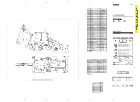
Machine locations are repeated for components located close together. A = Located inside cab. B = Located inside right console.
Form Number 143-0539
SENR3828
Machine Troubleshooting:
KENR8849
Engine Troubleshooting:
KENR6900
D = Located in or near relay panel.
Resistor, Sender and Solenoid Specifications Part No. 134-2540
MACHINE CONNECTOR & COMPONENT LOCATIONS
Component Description Resistor:
Resistance (Ohms)¹
CAN Terminating
120
244-3106
Sender:
Coolant Temperature
54°C (130°F) - 560 to 716 110°C (230°F) - 72 to 82
4W-9972
Sender:
Converter Temperature
54°C (130°F) - 560 to 716 110°C (230°F) - 72 to 82
303-2933
Sender:
Fuel Level (Non-EST)
Empty - 246-252 Full - 27-33
¹ At room temperature unless otherwise noted.
Connector Location Volume 1 Schematic Location
Machine Location
CONN 1
D-14
B
CONN 3
H-12
1
CONN 4
H-12
1
CONN 6
C-11
B
CONN 7
C-11
B
Connector Number
CONN 8
C-11
B
CONN 9
D-11
B
CONN 10
D-11
B
CONN 11
E-11
B
CONN 12
J-12
3
CONN 13
J-12
3
CONN 15
E-8
6
CONN 18
E-3
6
CONN 19
E-3
6
CONN 20
F-3
2
CONN 21
G-3
6
CONN 22
H-3
6
CONN 24
J-3
7
CONN 26
J-3
6
The connectors shown in this chart are for harness to harness connectors. Connectors that join a harness to a component are generally located at or near the component. See the Component Location Chart.
Off Machine Switch Specification Part No. 311-7711
Function
Actuate
Boosted Brake Pressure
3000 kPa MAX @ -40 C (435.1 psi) to +121 C
Deactuate 2387 ± .345 kPa @ -40 C (346 ± 0.05 psi) to +121 C
Contact Position Normally Closed
(Dimensions: 48 inches x 35 inches)
Wire Description Wire Number
36 Page,
KENR8979-01 VOL 1 of 2
KENR8979-01 May 2011