Item
Part Number
1 2 3 4 5 6 7 8 9 10 11 12 13 14 15 16 17 18 19 20 21* 22 23 24 25 26 27 28 29 30 31 32A 32B 33 34 35 36 37 38 39 40 41 42 43 44A 44B 45 46 47 48 49 50 51 52 53 54 55 56 57 58 59 60 61 62 63* 64
178-7480 167-4235 238-8550 162-3960 190-8315 206-3553 9T-0704 9T-0704 124-8818 185-1839 188-7471 168-0361 206-3549 131-9203 130-6520 188-7471 185-5906 185-5907 180-9588 240-9716 ----143-0421 185-5902 192-0827 206-0520 206-0522 192-0827 186-3629 185-5898 239-2226 179-5593 202-2236 200-0161 206-3628 6E-6285 191-8161 137-9466 187-0524 206-0518 206-0514 9T-0704 206-0503 191-7725 190-3450 6E-4158 193-9189 3E-8622 190-3402 6E-6281 190-3400 187-0527 180-8592 180-8593 180-8594 166-7950 190-3397 6E-6284 190-3450 206-3685 203-5489 203-5490 203-5533 185-5901 191-4010 ----178-7481
FLUID POWER SYMBOLS
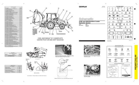
RENR7782 January 2004
Component Locations Schematic Location
Description
Back Pressure Check Valve (Return Oil) Steering Cylinder Metering Pump Ride Control Accumulator Ride Control Solenoid Valve Tilt Cylinder Line Relief Valve for Head End of Tilt Cylinder Line Relief Valve for Rod End of Tilt Cylinder Auxiliary Control Valve Multipurpose Bucket Cylinder (If Equipped) Auxiliary Relief Valve Loader Tilt Control Valve Loader Lift Cylinders Pressure Switch Loader Lift Control Valve Steering Priority Valve Two Bank Vavle for Loader Three Bank Valve for Loader Piston Pump Hydraulic Tank Hydraulic Oil Cooler Hydraulic Oil Filter Pilot Valve Stabilizer Control Valve Stabilizer Cylinder Stabilizer Cylinder Stabilizer Control Valve Return Manifold Stabilizer Contol Valve (Two Bank) Pressure Reducing Valve Lockout Solenoid Valve (If Equipped) Side Shift Bank Valve Cover (If Equipped) Center Pivot Bank Valve Cover (If Equipped) Boom Cylinder Line Relief for Rod End of Boom Cylinder Swing Cylinders Line Relief For Rod End of Swing Cylinder Line Relief for Head End of Backhoe Bucket Cylinder Backhoe Bucket Cylinder Backhoe Bucket Cylinder (Extendable Stick) Line Relief Valve for the Head End of Stick Cylinder Stick Cylinder Extendable Stick Cylinder (If Equipped) Extendable Stick Control Valve (If Equipped) Side Shift Bank Valve Cover (If Equipped) Center Pivot Bank Valve Cover (If Equipped) Side Shift Valve Stick Control Valve Line Relief for Rod End of Stick Cylinder Backhoe Bucket Control Valve Line Relief for Rod End of Backhoe Bucket Cylinder Backhoe Control Valve (Four Bank) Backhoe Control Valve (Five Bank) (Attachment) Backhoe Control Valve (Six Bank) (Attachment) Swing Control Valve Boom Control Valve Line Relief for Head End of Boom Cylinder Auxilary Control Valve (If Equipped) Swing Cushion Crossover Relief Valve (If Equipped) Backhoe Control Vavle (Four Bank) (Attachment - TUV) Backhoe Control Valve (Five Bank) (Attachment - TUV) Backhoe Control Valve (Six Bank) (Attachment - TUV) Pilot Valve (Two Bank) (Pilot Lever with Switch) Outlet Cover Steer Cylinder (AWD) Back Pressure Check Valve (Hammer Option)
41
D-11 E-10 D-10 E-9 D-9 E-9 E-8 E-8 E-8 F-8 F-8 D-8 D-8 D-9 D-8 C-8 C-8 C-8 C-10 C-11 C-11 D-11 E-7 E-5, E-4 F-4 F-3 E-3 E-7 D-6 D-6 C-7 C-7 A-8 C-6 C-6 C-5 C-5 C-4 C-4 C-4 C-3 C-3 C-2 C-2 C-1 A-2 C-1 B-3 B-3 B-4 B-4 B-4 B-4 B-4 B-5 B-5 B-6 B-6 C-4 B-4 B-4 B-4 E-7 F-8 E-10 D-11
BASIC COMPONENT SYMBOLS
3
MAIN AUX.
PUMP or MOTOR
CONTROL VALVES
SPRING
FLUID CONDITIONER
LINE RESTRICTION (FIXED)
RESTRICTION
PUMP: VARIABLE and PRESSURE COMPENSATED
2-SECTION PUMP
20 42
PRESSURE COMPENSATION
LINE RESTRICTION (VARIABLE)
SPRING (ADJUSTABLE)
VARIABILITY
13
HYDRAULIC PNEUMATIC ENERGY TRIANGLES
ATTACHMENT
LINE RESTRICTION VARIABLE and PRESSURE COMPENSATED
VALVES VALVE ENVELOPES
VALVE PORTS
21 TWO POSITION
ONE POSITION
TWO-WAY
THREE POSITION
CONTROL VALVES
CHECK VALVES
AB
AB
P T SHIFTED POSITION
P T NORMAL POSITION
6
FOUR-WAY
THREE-WAY
INFINITE POSITION
SPRING LOADED
BASIC SYMBOL
MEASUREMENT
38 39 PRESSURE
ROTATING SHAFTS
FLOW
TEMPERATURE
UNIDIRECTIONAL
BIDIRECTIONAL
FLUID STORAGE RESERVOIRS
416D and 424D Backhoe Loader Hydraulic System
33
416D: BGJ1050-Up
424D: RXA1-UP CJZ1-UP
VENTED
RETURN ABOVE FLUID LEVEL
PRESSURIZED
RETURN BELOW FLUID LEVEL
COMBINATION CONTROLS
SOLENOID or MANUAL
SOLENOID
SERVO
SOLENOID and PILOT or MANUAL
SOLENOID and PILOT
DETENT
THERMAL
MANUAL CONTROL SYMBOLS
23 PUSH-PULL LEVER
PEDAL
PUSH BUTTON
GENERAL MANUAL
SPRING
PILOT CONTROL SYMBOLS
31 32A 32B 34 36 37 40 43
RELEASED PRESSURE
10
44A 44B 45 46 47
48 49 50
51
52 53 54
55
4
35 57
INTERNAL RETURN
2
56
19 22
7
8
CROSSING AND JOINING LINES
ACCUMULATORS
SPRING LOADED
28
SIMPLIFIED
GAS CHARGED
LINES CROSSING
9 11 12 15 16 17 18 HYDRAULIC PUMPS FIXED DISPLACEMENT
416D, 424D SINGLE TILT LOADER WITH CENTER PIVOT OR SIDE SHIFT BACKHOE
HYDRAULIC AND PNEUMATIC CYLINDERS
SINGLE ACTING
LINES JOINING
FIXED DISPLACEMENT
VARIABLE DISPLACEMENT NON-COMPENSATED
UNIDIRECTIONAL
UNIDIRECTIONAL
BIDIRECTIONAL
BIDIRECTIONAL
DOUBLE ACTING
INTERNAL PASSAGEWAYS
HYDRAULIC MOTORS
VARIABLE DISPLACEMENT NON-COMPENSATED
INTERNAL SUPPLY PRESSURE
COMPLETE
5 14
24 27 29 30
25 26
EXTERNAL RETURN
REMOTE SUPPLY PRESSURE
TWO POSITION
THREE POSITION
INFINITE POSITIONING
PARALLEL FLOW
FLOW IN ONE DIRECTION
CROSS FLOW
FLOW ALLOWED IN EITHER DIRECTION
Printed in U.S.A.
© 2004 Caterpillar All Rights Reserved
Electrical Symbols Table
* Part number not available at time of publication.
Hydraulic Symbols (Electrical)
CC
BB
G
52 Transducer (Fluid)
B
Transducer (Gas / Air)
M
Generator
Electric Motor
19
Description PUMP SIGNAL PRESSURE TEST PORT PUMP PRESSURE TEST PORT PILOT PRESSURE TEST PORT
Schematic Location C-9 B-9 E-5
Pressure Reducing Valve (Stabilizer) (52), Pilot Oil Pressure Test Port (CC)
4
B
Hydraulic Pump (19), Signal Pressure Test Port (AA)
Pressure Switch (Adjustable)
Pressure Switch
Electrical Symbols (Electrical)
Ride Control Pressure Switch F738-WH 200-BK
LEFT SIDE VIEW
Side Shift Lock Solenoid H771-BR 200-BK
Ride Control Solenoid 976-OR 200-BK
14
T
Pressure Symbol
45
C
Temperature Symbol
Electrical Schematic Example
420D Backhoe Loader (BKC)
SEBP3584
432D Backhoe Loader (WEP & TDR)
SEBP3971
Specifications: (Hydraulic & Steering System)
RENR7778
Testing and Adjusting: (Hydraulic & Steering System)
RENR7779
Specifications: (Axles, Differentials & Brakes)
RENR7776
Testing and Adjusting: (Axles, Differentials & Brakes)
RENR7777
Harness identification code This example indicates wire 135 in harness "AG".
4
AA
SEBP3967
Machine System
Current Standard
Current Standard
Media Number
420D Backhoe Loader (BMC)
Wire Circuit Number Identification
19
Wire Color
325-AG135 PK-14
C
325-PK Circuit Identification Number
SECTION B-B SECTION C-C
Electrical System Schematic: (Electrical system)
Hydraulic Schematic Example
50 51 52 SEBP3583
442D Backhoe Loader (TBD & SMJ)
Flow Symbol
Level Symbol
Wire Number Identification Codes
5
Related Manuals Description Parts Manual
Electrical Wire
Temperature Switch
Wire Color
Wire Gauge
Previous Standard
RENR7781
RIDE CONTROL
Wire Color
Wire
325-PK-14
Hydraulic Pump (19), Pump Pressure Test Port (BB)
Accumulator (4) , Pressure Switch (14), Ride Control Valve (5)
Backhoe Valve (50, 51 or 52) , Side Shift Clamp Valve (45)
B Circuit Number Identification
A
Wire Gauge (EXAMPLE VALVE)
20 Page, B/W, DGM
Tap Number AA BB CC
RENR7782-00
Tap Locations Pressure, Sampling, and Sensor