Component Locations Part Number
Machine Location
Schematic Location
Cooler Gp
154-3799
1
C-14
Cover Gp - Inlet
200-0161
43
C-9
Cover Gp - Outlet
6E-4158
2
C-2
Cover Gp - Steer Priority Valve
191-4010
3
H-10
Cylinder Gp - Boom
206-3628
5
D-8
Cylinder Gp - Bucket, Std
206-0514
6
D-5
Description
FLUID POWER SYMBOLS
RENR3586-03 January 2005
BASIC COMPONENT SYMBOLS MAIN AUX.
PUMP or MOTOR
LINE RESTRICTION (FIXED)
RESTRICTION
PRESSURE COMPENSATION
LINE RESTRICTION (VARIABLE)
SPRING (ADJUSTABLE)
VARIABILITY
CONTROL VALVES
SPRING
FLUID CONDITIONER
PUMP: VARIABLE and PRESSURE COMPENSATED
2-SECTION PUMP
HYDRAULIC PNEUMATIC ENERGY TRIANGLES
ATTACHMENT
LINE RESTRICTION VARIABLE and PRESSURE COMPENSATED
VALVES VALVE ENVELOPES
VALVE PORTS
TWO POSITION
ONE POSITION
TWO-WAY
THREE POSITION
FOUR-WAY
THREE-WAY
Cylinder Gp - (ST) Lift 416D
BKG
1-Up
CONTROL VALVES
206-3549
424D
416D
BKJ
1-1049
206-3549
BFP
5178-Up
206-3549
BGP
397-Up
206-3549
BKR
418-Up
206-3549
B2D
1-Up
230-0979
BGJ
1050-1140
230-0979
BFP
12900-Up
230-0979
PRESSURE
7
I-5
228-3500
8
I-3
Cylinder Gp - Steer
167-4235
9
F-14
Cylinder Gp - Stick
235-9829
10
D-4
Cylinder Gp - Swing
228-3506
11
D-7
Cylinder Gp - Swing
228-3506
12
D-7
Cylinder Gp - Tilt, ST
206-3553
13
F-12
Filter Gp
210-6243
14
H-15
Manifold - Return
186-3629
19
E-14, C-8
Pump Gp - Metering, HMU
238-8550
15
F-15
16
B-12
424D
235-4108
Tank Gp - Hydraulic
PILOT CONTROLLED
ROTATING SHAFTS
FLOW
TEMPERATURE
UNIDIRECTIONAL
BIDIRECTIONAL
FLUID STORAGE RESERVOIRS
228-3499
245-8998
SHUTTLE
SPRING LOADED
BASIC SYMBOL
MEASUREMENT
Cylinder Gp - Stabilizer, RS
416D
INFINITE POSITION
E-12
Cylinder Gp - Stabilizer, LS
Pump Gp - Piston
P T SHIFTED POSITION
P T NORMAL POSITION
4
CHECK VALVES
AB
AB
BB
AA
416D and 424D Backhoe Loader Hydraulic System 416D: BKG1-UP BFP1-UP B2D1-UP BGJ1-UP
42 16
424D: BGP1-UP BKR1-UP
VENTED
RETURN ABOVE FLUID LEVEL
PRESSURIZED
RETURN BELOW FLUID LEVEL
COMBINATION CONTROLS
SOLENOID or MANUAL
SOLENOID
SERVO
SOLENOID and PILOT or MANUAL
SOLENOID and PILOT
DETENT
THERMAL
MANUAL CONTROL SYMBOLS
MANUAL SHUTOFF
PUSH-PULL LEVER
GENERAL MANUAL
PUSH BUTTON
PEDAL
SPRING
PILOT CONTROL SYMBOLS
Valve Group - Stabilizer, 2 Bank (42), Pilot Oil Pressure Test Port (AA)
RELEASED PRESSURE
Hydraulic Pump (16), Signal Pressure Test Port (BB)
REMOTE SUPPLY PRESSURE
240-9721
17
B-13
180-8592
53
C-6
Valve Gp - Control, Boom
190-3397
21
C-7
Valve Gp - Control, Bucket
190-3400
22
C-5
Valve Gp - Control, Lift
130-6520
23
E-10
185-5898
42
E-7
Valve Gp - Control, Stabilizer
192-0827
39
H-6, H-3
Valve Gp - Control, Steer Priority
188-7471
24
D-11
UNIDIRECTIONAL
UNIDIRECTIONAL
185-5906
25
D-11
BIDIRECTIONAL
BIDIRECTIONAL
Valve Gp - Control, Stick
190-3402
26
C-4
Valve Gp - Control, Swing
166-7950
27
C-7
Valve Gp - Control, Tilt
168-0361
28
F-10
Valve Gp - Pilot, 2 Bank
185-5902
37
G-8
Valve Gp - Reducing, Stabilizer
239-2226
41
F-7
Valve Gp - Relief, Boom
6E-6284
31
C-8
Valve Gp - Relief, Boom
6E-6285
35
C-8
Valve Gp - Relief, Bucket
187-0524
33
C-5
Valve Gp - Relief, Bucket
187-0527
30
C-5
Valve Gp - Relief, Stick
6E-6281
29
C-4
Valve Gp - Control, Backhoe
EXTERNAL RETURN
INTERNAL RETURN
SIMPLIFIED
INTERNAL SUPPLY PRESSURE
COMPLETE
4 Bank
CROSSING AND JOINING LINES
ACCUMULATORS
SPRING LOADED
Valve Gp - Control, Relief
GAS CHARGED
LINES CROSSING
HYDRAULIC PUMPS
HYDRAULIC AND PNEUMATIC CYLINDERS
SINGLE ACTING
LINES JOINING
DOUBLE ACTING
INTERNAL PASSAGEWAYS
HYDRAULIC MOTORS
Stabilizer, 2 Bank FIXED DISPLACEMENT
VARIABLE DISPLACEMENT NON-COMPENSATED
FIXED DISPLACEMENT
VARIABLE DISPLACEMENT NON-COMPENSATED
THREE POSITION
INFINITE POSITIONING
Valve Gp - Control, Steer Priority PARALLEL FLOW
FLOW IN ONE DIRECTION
CROSS FLOW
TWO POSITION
FLOW ALLOWED IN EITHER DIRECTION
2 Bank Loader
Valve Gp - Relief, Stick
9T-0704
32
C-4
Valve Gp - Relief, Swing
137-9466
34
C-7
Valve Gp - Relief, Tilt
9T-0704
36
H-10
Volume 1: Single Tilt Loader with Center Pivot Backhoe Printed in U.S.A.
© 2005 Caterpillar All Rights Reserved
37 38
Electrical Symbols Table Hydraulic Symbols (Electrical)
17
Attachments
15 44
D-3
Cylinder Gp - E Stick Bucket
206-0518
45
D-5
Cylinder Gp - MP Bucket
185-1839
46
H-12
Valve Gp - Control, Aux
124-8818
48
G-10
Valve Gp - Control, Aux
190-3450
52
C-9
203-5489
20
C-6
10
G
6 45 Transducer (Fluid)
Transducer (Gas / Air)
M
Generator
Electric Motor
13
Valve Gp - Control, Backhoe 4 Bank With TUV
1
5
Valve Gp - Control, Backhoe 203-5490
49
C-6
5 Bank With TUV
Pressure Switch (Adjustable)
Pressure Switch
Valve Gp - Control, Backhoe 203-5533
50
C-6
190-3450
51
C-2
180-8593
54
C-6
180-8594
55
C-6
Electrical Wire
Temperature Switch
6 Bank With TUV Valve Gp - Control, E Stick
Electrical Symbols (Electrical)
Valve Gp - Control, Side Shift 5 Bank
44
Valve Gp - Control, Side Shift
T
6 Bank
Pressure Symbol
CC
Valve Gp - Control, Steer Priority 185-5907
56
D-11
Valve Gp - Pilot, 2 Bank
185-5901
38
G-8
Valve Gp - Relief
9T-0704
58
F-11, H-11
59
F-14
Temperature Symbol
Flow Symbol
Level Symbol
3 Bank Loader
16
Wire Number Identification Codes
All Wheel Steer Cylinder Gp - AWD Steer
214-5097
Electrical Schematic Example
Ride Control
7
Accumulator Gp - Ride Control
162-3960
60
F-13
Switch As - Pressure
131-9203
61
D-12
Valve Gp - Mounting
416D
243-2266 62
424D
E-13
222-1684
Hydraulic Pump (16), Pump Pressure Test Port (CC)
8
Tap Number
Description
27 29 30 31 32
58
Schematic Location
AA
Pilot Pressure Test Port
H-7
BB
Signal Pressure Test Port
C-11
CC
Pump Pressure Test Port
A-11
Harness identification code This example indicates wire 135 in harness "AG".
Wire Circuit Number Identification
Wire Color
325-AG135 PK-14 325-PK
33 34 35 43 49
Tap Locations Pressure, Sampling, and Sensor
Current Standard
Current Standard
2 20 21 22 26
50 51 53 54 55
Hydraulic Schematic Example
11 12
39 40
60 61 62
19
4
9 59
46
Circuit Identification Number
41 42
Wire Color
Wire Gauge
Previous Standard
14 16 3
23 24 25 28 36 48 52 56
Wire Color
Wire
325-PK-14 B Circuit Number Identification
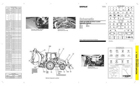
Machine Component Locations
A
Wire Gauge (EXAMPLE VALVE)
20 Page, RBM
191-7725
RENR3586-03 VOL 1
Cylinder Gp - E Stick