27
CONN 28 CONN 29
CONN 38
191
200
CONN 10
CONN 4
40
CONN 5
CONN 6 CID
Component
0041
CONN 26
76
CONN 9 CONN 1 CONN 8
134
192
CONN 13
186
182
CONN 36 CONN 35
CONN 21
107 52
185
122 CONN 33
32
CONN 3
CONN 18
35
CONN 11
55
CONN 15
CONN 32 77
CONN 25 CONN 27
125
145
54
24
CONN 31
22
21
184
CONN 12
48
71
CONN 22 183 165 171 201 155 193 194 157
152 154
1
2
50
Solenoid - Implement Lockout
4
Solenoid - LH Lock Valve
B-4
106
E-1
5
Solenoid - LH Stab Detent
I-14
107
Alternator
0268
Programmed Parameter Fault
Battery
F-2
6
Solenoid - Loader Aux Valve 1
I-10
108
Ride Control Switch
Block As - Fuse
E-5
7
Solenoid - Loader Aux Valve 1
G-14
109 110
0368
Transmission Auto/Manual Switch
Buss Bar 1
H-5
8
Solenoid - Loader Aux Valve 2
I-10
0490
Implement Lockout Switch
Buss Bar 2
H-5
9
Solenoid - Loader Aux Valve 2
G-14
111
0491
3rd Function Forward Solenoid
Buss Bar 3
H-4
10
Solenoid - Loader QC
A-14
112
0517
All Wheel Drive Switch
Control Gp - AWS
A-8
11
Solenoid - Lockout
F-16
113
Control Gp - Handle (Loader)
B-8
12
Solenoid - Lockup Clutch
J-1
114
0590
Engine Control Module
0597
Main Hydraulic Pump Discharge Pressure Sensor
Control Gp - Joystick (RH)
H-14
13
Solenoid - Pattern Changer 1
J-10
115
0600
Hydraulic Oil Temperature Sensor
Control Gp - Joystick LH
J-10
14
Solenoid - Pattern Changer 1
G-14
116
0626
Steering/Transmission Lock Switch
Control Gp - Joystick LH
G-13
15
Solenoid - Pattern Changer 2
I-10
117
Control Gp - Joystick RH
I-10
16
Solenoid - Pattern Changer 2
G-14
118
0629
Neutralizer Switch
0637
Backup Alarm
Control Gp - Machine
H-7
17
Solenoid - REV
I-1
119
0679
Torque Converter Lockup Clutch Solenoid
Control Gp - RH Backhoe
G-13
18
Solenoid - REV STD
H-1
120
0702
Transmission Gear Lever Selector Sensor (Switch)
Diode - 1
E-16
19
Solenoid - RH Lock Valve
B-4
121
Diode - 2
E-16
20
Solenoid - RH Stab Detent
H-14
122
0769
Lift Cylinder Rod End Pressure Sensor
0882
Implement Lockout Solenoid
Diode - Blocking 1
B-6
21
Solenoid - Ride Cont 1
A-13
123
1251
Alternator R-Terminal Signal
Diode - Blocking 2
B-6
22
Solenoid - Ride Cont 2
A-13
124
1401
Transmission Solenoid 1
Diode - Fuel Lift Pump
C-5
23
Solenoid - RTD Loader
C-8
125
Transmission Solenoid 2
Diode - Lights (FR)
C-10
24
Solenoid - Side Shift Left
F-16
126
1403
Transmission Solenoid 3
Diode - Lights (RR)
C-10
25
Solenoid - Side Shift Lock
G-14
127
1404
Transmission Solenoid 4
Diode - Rev Sol
H-1
26
Solenoid - Side Shift Right
F-16
128
1405
Transmission Solenoid 5
Diode - Roading
C-10
27
Solenoid - Speed Clutch 1
I-1
129
1406
Transmission Solenoid 6
Flasher
D-5
28
Solenoid - Speed Clutch 2
I-1
130
1529
Quick Coupler Switch
Fuel Water Separator
F-1
29
Solenoid - Speed Clutch 3
I-1
131
2236
Hoe Auxiliary Valve #1 Port A Solenoid
Glow Plugs
E-1
30
Solenoid - STD AWD
H-1
132
2237
Hoe Auxiliary Valve #1 Port B Solenoid
Ground - Cab RF
D-11
31
Stud - Cab Power
F-2
133
Ground - Control
D-7
32
Stud - Jump Start
F-2
134
2242
Loader Auxiliary Valve Port A Solenoid
2243
Loader Auxiliary Valve Port B Solenoid
Ground - ECM Cab
E-8
33
Stud - Power
F-2
135
2244
Hoe Auxiliary Valve #2 Port A Solenoid
Ground - Engine
G-2
34
Suppressor - HVAC
G-1
136
2245
Hoe Auxiliary Valve #2 Port B Solenoid
Ground - Lower Cab
D-7
35
Suppressor - Load Check Disable 1
B-4
137
Loader Joystick Thumbwheel Position Sensor
Ground - Upper Cab
J-12
36
Suppressor - Load Check Disable 2
B-4
138
Hoe Left Joystick Thumbwheel Position Sensor
Ground - Upper Cab
I-8
37
Suppressor - Lockout Sol
E-16
139
Horn - Forward
E-1
38
Suppressor - Pattern Changer
I-10
140
2531
Hoe Right Joystick Thumbwheel Position Sensor
2735
Loader Auxiliary Continuous Flow Switch
Horn - RR
F-14
39
Suppressor - QC 3
B-14
141
2736
Hoe Auxiliary Continuous Flow Switch
Motor - Blower
A-12
40
Suppressor - QC 4
A-14
142
3709
All Wheel Drive (AWD) Solenoid
Motor Gp - Front Washer
F-1
41
Suppressor - QC 5
A-14
143
Main Hyd Pump Displacement Limit Sol (Hyd Torque Limit Sol)
Motor Gp - Front Wiper
J-6
42
Suppressor - Ride Cont
B-13
144
Motor Gp - Front Wiper
D-11
43
Suppressor - RTD
C-8
145
Motor Gp - Fuel Lift Pump
E-1
44
Suppressor - Side Shift Left
F-16
146
Motor Gp - Rear Washer
F-1
45
Suppressor - Side Shift Right
F-16
147
Motor Gp - Rear Wiper
J-8
46
Suppressor - SS Lock
G-14
148
Motor Gp - Rear Wiper
149
Condition
CONN 19
190
181
110
11
111
180
62 101
144
60
167
197 156 174 163 159
126
198
178
179
160
176
196
166
148
147
146
82
202
19
139
96
151
50
Switch - Attach Front Work Lamp
C-15
152
51
Switch - Attach Rear Work Lamp
I-16
153
Radio - Product Link
J-2
52
Switch - Attach Rear Work Lamp
C-15
154
Relay - A/C Shutoff
B-10
53
Switch - Auto Man
F-8
155
Relay - Dead Engine Lower Command
A-4
54
Switch - AWD
G-8
156
E282
Implement Hydraulic Oil Filter Restricted
E360
Low Engine Oil Pressure
E361
High Engine Coolant Temperature
E391
Inlet Air Restriction
Relay - Dead Engine Lower Enable
B-4
55
Switch - AWS
A-9
157
E627
Parking Brake Applied With Machine In Motion
Relay - Fuel Lift Pump
C-5
56
Switch - Batt Disconnect
E-2
158 159
E861
Clock Manual Alignment Required
Relay - FWD Horn
G-5
57
Switch - Beacon
E-8
E875
Low System Voltage
Relay - Hi Spd
A-10
58
Switch - Blower Speed
A-12
160
E876
High System Voltage
Relay - Neutral Start
C-5
59
Switch - Brake LH
G-9
161
E878
High Hydraulic Oil Temperature
Relay - POS Lamp
F-5
60
Switch - Brake RH
G-9
162
Relay - Rear Horn
F-5
61
Switch - Broom Angle
A-16
163
Stabilizer Raised While Transmission In Gear
Failure Description
0
Data valid but above normal operational range.
1
Data valid but below normal operational range.
2
Data erratic, intermittent, or incorrect.
3
Voltage above normal or shorted high.
4
Voltage below normal or shorted low.
5
Current below normal or open circuit.
6
Current above normal or grounded circuit.
7
Mechanical system not responding properly.
8
Abnormal frequency, pulse width, or period.
9
Abnormal update.
10
Abnormal rate of change.
11
Failure mode not identifiable.
12
Bad device or component.
13
Out of calibration.
14
Parameter failures.
15
Parameter failures.
16
Parameter not available.
17
Module not responding.
18
Sensor supply fault.
19
Condition not met.
20
Parameter failures.
61
57
NOT SHOWN
63
Relay - Ride Control
F-5
62
Switch - Column Multi Function
E-9
164
Relay - Stab
I-12
63
Switch - Cont Flow
A-16
165
Relay - Start
F-3
64
Switch - Cont Flow 7-8
J-16
166
Relay As - PRM Module 1
H-5
65
Switch - Cont Flow 7-8
D-15
167
Relay As - PRM Module 2
H-5
66
Switch - Control Pattern
H-9
168
Relay As - PRM Module ENG
H-4
67
Switch - Crab Circle
A-9
169
Relay As - PRM Module HVAC
H-4
68
Switch - Diff Lock
G-9
170
Resistor - Can Terminating 1
D-9
69
Switch - Elect Ext Power
A-16
171
Resistor - Can Terminating 2
H-12
70
Switch - Engine Oil Pressure
F-1
172
Resistor - Motor SPD
A-12
71
Switch - Float Detent Pressure
B-4
173
Sender - Conv Temp
I-1
72
Switch - FNR Control Manual
F-9
174
Sender - Conv Temp
H-1
73
Switch - Hazard
D-8
175
Sender - Coolant Temp
F-1
74
Switch - Heater AC
B-12
176
Sender - Fuel Level
F-1
75
Switch - Hyd Oil Filter Bypass
G-1
177
Sensor - Bucket POS
C-8
76
Switch - Implement Lockout
B-15
178
Sensor - FR Axle Pos
A-10
77
Switch - Implement Lockout
H-16
179
Sensor - Hyd Load Auto
I-3
78
Switch - Key
I-16
180
Sensor - Hyd Load STD
H-3
79
Switch - Key
C-16
181
Sensor - Hyd Oil Temp
G-1
80
Switch - LH Stab
I-14
182
Sensor - Ride Control
A-14
81
Switch - Loader QC Pins
B-16
183
Sensor - RR Axle Pos
A-6
82
Switch - Neut Loader Handle
E-3
184
Sensor - XMSN Out SPD STD
H-3
83
Switch - Neut XMSN Handle
E-3
185
Sensor - XMSN Out Speed
I-3
84
Switch - Park Brake
D-14
186
Solenoid - AC Compressor Clutch
G-1
85
Switch - Pressure (Stability)
C-11
187
Solenoid - AWD
I-1
86
Switch - Rear Fog Lamp
H-8
188
Solenoid - Cold Start ADV
E-1
87
Switch - Rear Wiper
J-16
189
Solenoid - Diff Lock
J-1
88
Switch - Rear Wiper
D-15
190
Solenoid - Diff Lock STD
H-1
89
Switch - Return to Dig
C-8
191
Solenoid - Fuel Shutoff Turbo
E-1
90
Switch - RH Stab
I-14
192
Solenoid - FWD High
I-1
91
Switch - Ride Cont
F-8
193
Solenoid - FWD Low
I-1
92
Switch - Roading
F-8
194
Solenoid - FWD Low STD
H-1
93
Switch - Side Shift Lock
D-15
195
Solenoid - Hoe Aux Valve 1
J-10
94
Switch - Stability Warn
C-12
196
Solenoid - Hoe Aux Valve 1 - 1
H-14
95
Switch - Start Aid
I-16
197
Solenoid - Hoe Aux Valve 1 - 2
H-14
96
Switch - Start Aid
C-15
198
Solenoid - Hoe Aux Valve 2
J-10
97
Switch - Start Aid (Cold Adv)
E-1
199
Solenoid - Hoe Aux Valve 2 - 1
H-10
98
Switch - Thermostat
A-12
200
Solenoid - Hoe Aux Valve 2 - 1
F-13
99
Switch - XMSN Lock
G-8
201
Solenoid - Hoe Aux Valve 2 - 2
H-10
100
Valve Gp - AWS
A-6
202
Solenoid - Hoe Aux Valve 2 - 2
F-13
101
Valve Gp - Pilot (Loader)
C-8
203
J-1
102
Solenoid - Hyd Torque Limit
65 69
58
68
53
56 CONN 24
23
420F: LTG1-UP LKH1-UP
430F: LNH1-UP LDY1-UP
8
9
10
432F: SEJ1-UP LNR1-UP
434F: LDH1-UP FLY1-UP
444F: LJJ1-UP FBN1-UP
© 2012 Caterpillar, All Rights Reserved
Printed in U.S.A.
Harness And Wire Electrical Schematic Symbols Symbols
T
Pressure Symbol
Temperature Symbol
Level Symbol
Flow Symbol
Circuit Breaker Symbol
Symbols and Definitions Fuse: A component in an electrical circuit that will open the circuit if too much current flows through it. Switch (Normally Open): A switch that will close at a specified point (temp, press, etc.). The circle indicates that the component has screw terminals and a wire can be disconnected from it. Switch (Normally Closed): A switch that will open at a specified point (temp, press, etc.). No circle indicates that the wire cannot be disconnected from the component. Ground (Wired): This indicates that the component is connected to a grounded wire. The grounded wire is fastened to the machine. Ground (Case): This indicates that the component does not have a wire connected to ground. It is grounded by being fastened to the machine. Reed Switch: A switch whose contacts are controlled by a magnet. A magnet closes the contacts of a normally open reed switch; it opens the contacts of a normally closed reed switch. Sender: A component that is used with a temperature or pressure gauge. The sender measures the temperature or pressure. Its resistance changes to give an indication to the gauge of the temperature or pressure.
T
Relay (Magnetic Switch): A relay is an electrical component that is activated by electricity. It has a coil that makes an electromagnet when current flows through it. The electromagnet can open or close the switch part of the relay. Solenoid: A solenoid is an electrical component that is activated by electricity. It has a coil that makes an electromagnet when current flows through it. The electromagnet can open or close a valve or move a piece of metal that can do work.
Connector Location Schematic Location
Connector Number
97
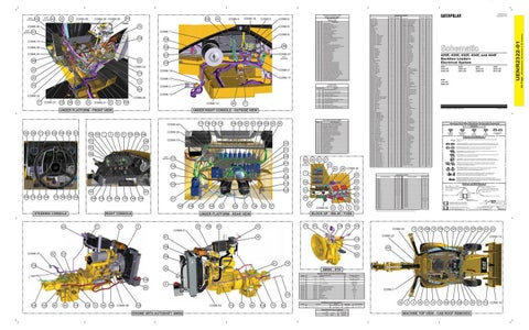
420F, 430F, 432F, 434F, and 444F Backhoe Loaders Electrical System
28 CONN 34
64
66 140
I-16
J-16
59
81
Switch - Attach Front Work Lamp
D-16
67
175 188 169 164
49
Panel Gp - Instrument
128 113
150
D-1
Panel Gp - Instrument
7
123
F-1
HighFuel/Water Separator Water Level
20 124
G-1
Switch - Air Filter
E232
100
127
Switch - A/C Refrigerant Pressure
48
Motor Gp - Starter
¹The FMI is a diagnostic code that indicates what type of failure has occurred.
NOT SHOWN
47
F-3
High Speed Directional Shift
FMI No.
99
C-13
Motor Gp - Seat
E153
CONN 30
51 153 195 189
151
95 108 109 98
105
3
Failure Mode Identifiers (FMI)¹
104 105 94
G-14
J-10
UNDER RIGHT CONSOLE - OUTSIDE VIEW
117 118 115 116
103 104
F-14
E979
UNDER PLATFORM - FRONT VIEW
H-1 I-10
Alarm - Backup
Event Code
203
Solenoid - Hyd Torque Limit STD Solenoid - Implement Lockout
8 Volt DC Supply
Event Codes Machine Control
CONN 2
1 2
Electrical System Voltage
3742
12
I-16 C-16
Transmission Output Speed Sensor
2530
CONN 17
Alarm - Action Alarm - Action
0168
2529
173
Machine Location
0191
1402
NOT SHOWN
Schematic Location
Component
Alarm - Backup
0367
NOT SHOWN 141
Machine Location
Schematic Location
Connector Number
CONN 1
A-11, C-16, I-16
CONN 22
B-12
CONN 2
F-15, G-12
CONN 23
B-11
CONN 3
C-13, J-14
CONN 24
D-9
CONN 4
C-13, I-14
CONN 25
C-9
CONN 5
C-13, I-14
CONN 26
A-9, B-9
CONN 6
B-13, I-14
CONN 27
A-9
CONN 7
E-13, E-14
CONN 28
C-8
CONN 8
E-14, I-13
CONN 29
C-8
CONN 9
D-13, E-14, I-13
CONN 30
A-7
CONN 10
D-13, J-13
CONN 31
B-6
CONN 11
A-10, D-14
CONN 32
J-3
CONN 12
B-13, I-14
CONN 33
J-1, J-2
CONN 13
A-14
CONN 34
J-2
CONN 14
A-14
CONN 35
H-2, H-3, I-2
CONN 15
A-14, F-3
CONN 36
H-2, H-3, I-2
CONN 16
A-13
CONN 37
G-2, G-3
CONN 17
H-12, I-9
CONN 38
E-3
CONN 18
G-12
CONN 39
G-1
CONN 19
F-12
CONN 40
E-1
CONN 20
C-12
CONN 41
E-1
CONN 21
B-12
Magnetic Latch Solenoid: A magnetic latch solenoid is an electrical component that is activated by electricity and held latched by a permanent magnet. It has two coils (latch and unlatch) that make electromagnet when current flows through them. It also has an internal switch that places the latch coil circuit open at the time the coil latches.
Harness and Wire Symbols Wire, Cable, or Harness Assembly Identification: Includes Harness Identification Letters and Harness Connector Serialization Codes (see sample).
Harness Identification Letter(s): (A, B, C, ..., AA, AB, AC, ...)
L-C12 3E-5179
AG-C4 111-7898
L-C12 3E-5179
1
Part Number: for Connector Plug
Harness Connector Serialization Code: The "C" stands for "Connector" and the number indicates which connector in the harness (C1, C2, C3, ...).
Part Number: for Connector Receptacle
2 Plug
Receptacle Pin or Socket Number
1 2
Deutsch connector: Typical representation of a Deutsch connector. The plug contains all sockets and the receptacle contains all pins.
1 2
Sure-Seal connector: Typical representation of a Sure-Seal connector. The plug and receptacle contain both pins and sockets.
5A Fuse (5 Amps)
9X-1123
Component Part Number
325-AG135 PK-14 Harness identification code: This example indicates wire group 325, wire 135 in harness "AG".
Wire Gauge Wire Color
The connectors shown in this chart are for harness to harness connectors. Connectors that join a harness to a component are generally located at or near the component. See the Component Location Chart.
STEERING CONSOLE
RIGHT CONSOLE
41
45
74
BLOCK GP - RELAY / FUSE
UNDER PLATFORM - REAR VIEW
30
5
150
90
73
44
93
26
120
79
103 CONN 20
CONN 41 87
92
131
18 168 16 170 17 161 33
70 137 106 42
CONN 23
29
43 CONN 14
132
199 CONN 37
13
83
187
89
158 91
119
78
38
XMSN - STD Resistor, Sender and Solenoid Specifications Part No.
136 6 85 177
Component Description
134-2540
Resistor:
244-3106
Sender:
Coolant Temp
321-1327
Sender:
Fuel Level (EST)
303-2933
Sender:
Fuel Level (NON-EST)
Resistance (Ohms)¹
Terminating
120 ± 10% 54°C (130°F) - 560 to 716 110°C (230°F) - 72 to 82 Empty: 246-252 Full: 27-33 Empty: 246-252 Full: 27-33 8.8 ± 0.4
305-3423
Solenoid:
248-3290
Solenoid:
AWD Diff Lock, STD AWD, Speed Clutch 1
8.8
240-6866
Solenoid:
Hoe AUX Valves - 7th Function
33.8
200-6210
Solenoid:
Hoe AUX Valves - 8th Function
9.88 ± 0.49
220-3398
Solenoid:
Implement Lockout
8 ± 0.5
212-3350
Solenoid:
Loader QC
273-3525
Solenoid:
Lockout
7.3
250-6148
Solenoid:
Pattern Changer
33.8
238-4628
Solenoid:
Ride Control
7.3
249-7160
Solenoid:
Side Shift Left / Right
8.8
CONN 7
3.2 ± 7%
¹ At room temperature unless otherwise noted.
Off-Machine Switch Specification
102
133
86
84
114
129
72
49
149
CONN 39
135
CONN 40
172
34
88
130
75
80
Part No. 134-0404
Function
Actuate 276 to 303 kPa Max (40 - 44 psi)
Hydraulic Bypass Oil Filter
Deactuate 207 kPa (30 psi)
Contact Position
39
3
4
46
47
14
15 162 121 138 31
Normally Open
Related Electrical Service Manuals
ENGINE WITH AUTOSHIFT XMSN
Title Starting Motor: Control:
Form Number 149-0539
SENR3828
Machine
UENR2484
MACHINE TOP VIEW - CAB ROOF REMOVED
36
37
112 CONN 16
(Dimensions: 56 inches x 35 inches)
25
Schematic Location
Component
42 Page,
NOT SHOWN 142
UENR2322-01 November 2012
Component Location
UENR2322-01
NOT SHOWN 143
Component Identifiers (CID¹) Module Identifier (MID²) Machine Control (MID No. 039)