Connector Location
Description
Wire Number
Power Circuits
Description
Wire Color
Schematic Location
Connector Number
Accessory Circuits (Continued)
Volume 2
A-14
-
CONN 1
101
RD
Bat (+)
E543
WH
Auxiliary Hydraulic Solenoid #1
102
RD
Roading Lamps
E544
GN
Auxiliary Hydraulic Solenoid #2
105
RD
Key SW
110
RD
Horn/Misc.
603
PK
Beacon Switch
111
RD
Signal Lamp
604
OR
Rear Stop/Tail/Turn Lamp
113
OR
Operator Monitoring
605
YL
Turn Signal Switch (LH)
115
RD
Power Port
606
GY
Turn Signal Switch (RH)
116
BR
Rear Flood Switch
607
PK
Front Flood Switch
117
YL
Rear Flood Switch
608
GN
Rear Flood Switch
118
GY
Front Wiper
610
OR
Front Roading Lamp Switch
119
PK
Rear Wiper
611
PU
High Beam Lamp
122
BU
HVAC Relay
614
PU
Backlighting
CONN 13
123
WH
Transmission
617
BR
LH Tail Lamp
CONN 14
128
PK
Bucket Position
618
YL
RH Tail Lamp
CONN 15
131
RD
Start Aid
619
GN
Low Beam Lamp
CONN 16
134
YL
Ride Control
620
WH
Front Flood Lamp
136
GN
All Wheel Steering
627
YL
Rear Fog Lamp
143
BR
All Wheel Drive
630
GY
Rear Flood Lamp
144
GY
Beacon
157
YL
Front Flood Switch
702
OR
Brake Switch (B)
158
BR
Front Flood Switch
710
GN
Lighting Circuits
Volume 1
3E-6449
Actuate
Hydraulic Temperature (446D Only)
E-15
-
57
CONN 3
C-14,I-14
-
59NA,60COS
CONN 4
C-14
I-6
57
CONN 5
I-12,I-13
-
62
CONN 6
I-12,I-13
-
62
CONN 7
G-12,G-13
-
63
CONN 8
A-11,D-11,B-15
-
64
CONN 9
D-11
I-6
63
CONN 10
F-9
A-2
A
CONN 11
F-9
I-12,C-14
A
CONN 12
F-9
D-10,A-8,F-6
A
Deactuate
Contact Position Normally
38 ± 3ºC
27ºC MIN
(100.4 ± 5.4ºF)
(80.6ºF MIN)
Closed
38 ± 3ºC
27º ± 3°C
Normally
(100.4 ± 5.4ºF)
(80.6º ± 5.4°F)
Open
T
34
CONN 2
E-7
Function
7N-0758
Hydraulic Temperature
7W-1238
Engine Oil Pressure
62.1 to 95.1 kPa (9 to 13.8 psi)
62.1 to 95.1 kPa (9 to 13.8 psi)
Normally
Hyd. Filter Pressure (446D Only)
110 to 138 kPa (16 to 20 psi)
86 to 103 kPa (12.5 to 15 psi)
Normally
107 ± 3ºC
98ºC MIN
Normally
(224.6 ± 5.4ºF)
(208.4ºF MIN)
Open
551 kPa Max
344 ± 20 kPa
A-C, Normally Closed
(80 psi)
(50 ± 3 psi)
A-B, Normally Open
3500 kPa Max
3000 ± 150 kPa
A-C, Normally Closed
(507.6 psi)
(435.1 ± 21.8 psi)
A-B, Normally Open
7X-8549 9W-1519
Coolant Temperature (446D Only)
128-5091
All Wheel Steer Pressure
131-9203
Loader Cylinder Pressure
134-0404
Hydraulic Filter Pressure
I-10
-
63
I-14
A
276 to 303 kPa (40 to 44 psi)
207 kPa (30 psi)
Normally
F-10
47 to 53°C
37 to 43°C
Normally
-
A
CONN 17
F-9
E-11
A
(117 to 127°F)
(99 to 109°F)
Closed
CONN 18
I-7,I-8
-
A
2200 kPa Max
1800 ± 175 kPa
Normally
CONN 19
D-8
E-12,E-13,B-7,B-8,F-7,F-8
A
(319 psi)
(261 ± 25.4 psi)
Closed
CONN 20
I-4
G-3
18
CONN 21
H-4
F-3
18
Speed Sensor
CONN 22
G-4
-
D
Control Circuits
194-2553
Float Detent Pilot Pressure
236-6923
Refrigerant Pressure (A\C)
160
PU
Air Inlet Heater
720
PU
Brake Switch (A)
CONN 23
G-4
-
D
163
WH
Aux. Hydraulics
752
YL
Forward Solenoid
CONN 24
F-4
-
D
² Contact position at the contacts of the harness connector.
170
RD
Radio/Dome Lamp
754
BU
Reverse Solenoid
CONN 25
H-4
-
10
180
RD
Air Suspension Seat
755
OR
Speed Clutch Solenoid #3
CONN 26
I-2
I-1
25
184
BU
Rear Hydraulics
762
YL
Hydraulic Flow Relay
CONN 27
I-4
-
10
766
GN
Transmission Neutral Switch
CONN 28
E-2,E-1
-
25
779
WH
Quick Coupler Solenoid
CONN 29
F-1
C-2
45
FMI No.
C701
YL
Autoshift Control
CONN 30
-
H-3
D
0
Data valid but above normal operational range.
-
B-15,B-14,G-10
A
1
Data valid but below normal operational range.
A
2
Data erratic, intermittent, or incorrect.
200
BK
Main Chassis
202
BK
Autoshift Control
Failure Mode Identifiers (FMI)¹ Failure Description
203
BK
Aux. Hydraulics Control
C720
BU
Transmission Neutral Lock Switch
CONN 31
218
BK
Shift Handle Control (SEE NOTE AK)
E701
PK
Ride Control Auto Switch
CONN 32
-
D-14,A-3
265
BK
Shift Handle Control (SEE NOTE AK)
E702
OR
Ride Control Enable Switch
CONN 33
E-10
E-12,E-13
A
3
Voltage above normal or shorted high.
AWS Circle Steer Solenoid
CONN 34
-
B-12
D
4
Voltage below normal or shorted low.
-
I-12,A-3
A
5
Current below normal or open circuit.
281 A250 301
BK BK BU
Autoshift Control
E764
OR
MSS Control
F738
WH
Loader Pressure Switch
CONN 35
Basic Machine Circuits
F739
GN
Dead Engine Lower Switch
CONN 36
-
H-11
18
6
Current above normal or grounded circuit.
F748
WH
Ride Control On Switch
CONN 37
F-2
H-11
18
7
Mechanical system not responding properly.
CONN 38
-
A-3
17
8
Abnormal frequency, pulse width, or period.
CONN 39
-
F-8,A-3
17
9
Abnormal update.
CONN 40
-
A-12
17
10
Abnormal rate of change.
CONN 41
-
A-2
A
11
Failure mode not identifiable.
CONN 42
-
B-3
A
12
Bad device or component.
CONN 43
-
B-2
A
13
Out of calibration.
CONN 44
-
G-10
A
14
Parameter failures.
CONN 45
-
H-10
10
CONN 46
-
I-10
D
15
Parameter failures.
CONN 47
-
H-9,H-6
D
16
Parameter not available.
CONN 48
-
F-10,F-11
A
17
Module not responding.
CONN 49
-
H-9
48
18
Sensor supply fault.
19
Condition not met.
20
Parameter failures.
Starter No. 1 Sol
304
WH
Starter Relay No. 1 Output
F765
BR
Transmission in Gear Relay
306
GN
Starter Relay Coil
F793
OR
Air Inlet Heater Relay
307
OR
Key Start Switch
G703
GN
Dead Engine Lower Command Relay
308
YL
Main Power Relay Coil
G726
GY
All Wheel Steer Shutoff Solenoid
309
GY
Alternator (D) Term.
G789
BR
All Wheel Steer Mode Select Switch
310
PU
Start Aid SW To Start Aid Relay
G795
OR
All Wheel Steer Mode Select Switch
321
BR
Hydraulic Temperature Switch
G796
YL
All Wheel Steer Mode Select Switch
322
GY
Warning Horn (Forward)
H730
BR
Speed Clutch Solenoid #2
326
PU
Engine Shutdown Relay
H731
GY
Speed Clutch Solenoid #1
327
PK
Fuel Lift Pump Relay
H767
BR
All Wheel Steer Mode Select Switch
338
PK
MSS Control
H768
BR
All Wheel Steer RH Steer Solenoid
367
BU
Rear Horn Switch
H769
BR
All Wheel Steer LH Steer Solenoid
382
PK
Start Aid Solenoid
H770
BR
All Wheel Steer Shutoff Solenoid
384
BU
Glow Plug Relay
H771
BR
Side Shift Lock Solenoid
CONN 52
-
G-7
48
A313
OR
Stabilizer Leg Alarm
H772
YL
Hydraulic Shutoff Solenoid
CONN 53
-
H-7
48
A346
BU
MSS Control
M733
PK
MSS Control
CONN 54
G-6
G-7
D
A347
GN
MSS Eng Relay Monitoring Circuits
A856
OR
Stabilizer Leg Timer
CONN 55
-
E-8,H-4
D
C883
GY
AWS Quick Coupler Relay
CONN 56
-
A-7,G-6
D
CONN 50
C-9
F-11
42
CONN 51
-
H-9
D
405
GY
Low Oil Pressure Lamp
C884
OR
Right Broom Angle Relay
CONN 57
-
B-6
42
406
PU
High Coolant Temperature Lamp
C885
PK
AWS Quick Coupler Relay
CONN 58
-
C-6
56
419
YL
Parking Brake Lamp
E803
YL
Left Broom Angle Relay
CONN 59
-
D-6
42
429
YL
All Wheel Steer Pos Gauge
E804
BU
Right Broom Angle Relay
CONN 60
-
H-3
18
430
BU
Dirty Air Filter Lamp
F846
PU
MSS LED Indicator
CONN 61
-
G-5
42
439
YL
Full Water Separator Lamp
F871
PU
All Wheel Steer LH Steer Solenoid
CONN 62
-
F-1
22
441
OR
Eng Coolant Temperature Gauge
F872
BU
All Wheel Steer RH Steer Solenoid
CONN 63
-
G-1
7
443
YL
Converter Temperature Gauge
F874
PK
Start Aid Timer
CONN 64
H-6
F-5
24
447
PK
Fuel Level Gauge
F877
WH
AWS Quick Coupler Relay
CONN 65
-
D-6
42
450
YL
Tachometer Gauge
F879
PK
AWS Quick Coupler Relay
CONN 66
-
E-5
D
483
BR
Low Brake Fluid Lamp
G848
GN
MSS LED Indicator
CONN 67
-
B-4
6
E455
BR
Hydraulic Temperature Switch
H809
YL
Stabilizer Leg Timer
CONN 68
E-3
-
D
G423
PK
Dirty Hydraulic Filter Lamp
H833
PU
Control Flow Switch
CONN 69
A-15
B-2
64
911
YL
AWD Switch
CONN 70
I-4
H-3
D
CONN 71
-
G-3,G-4
49
Accessory Circuits 500
BR
Wiper - Front (Park)
922
BR
Forward Solenoid
501
GN
Wiper - Front (Low)
923
GY
Reverse Solenoid
502
OR
Wiper - Front (HI)
944
OR
Cat Data Link (+)
Switch (Normally Open): A switch that will close at a specified point (temp, press, etc.). The circle indicates that the component has screw terminals and a wire can be disconnected from it. Switch (Normally Closed): A switch that will open at a specified point (temp, press, etc.). No circle indicates that the wire cannot be disconnected from the component. Ground (Wired): This indicates that the component is connected to a grounded wire. The grounded wire is fastened to the machine. Ground (Case): This indicates that the component does not have a wire connected to ground. It is grounded by being fastened to the machine.
275 to 1750 kPa¹
-Normally Open² (40 to 255 psi) ¹ With increasing pressure the closed condition can be maintained up to 2800 kpa (405 psi), with decreasing pressure the closed condition can be maintained down to 170 kpa (25psi).
Ground Circuits
Reed Switch: A switch whose contacts are controlled by a magnet. A magnet closes the contacts of a normally open reed switch; it opens the contacts of a normally closed reed switch.
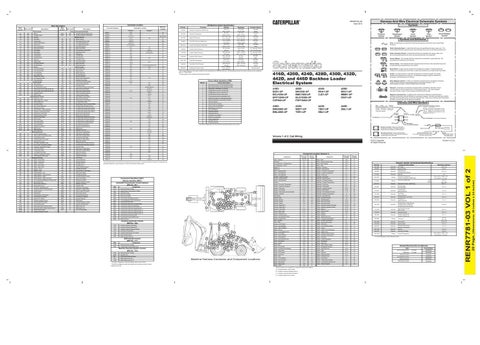
416D, 420D, 424D, 428D, 430D, 432D, 442D, and 446D Backhoe Loader Electrical System 416D: B2D1-UP BGJ1050-UP BFP12900-UP CXP940-UP
420D: BKC920-UP BMC1060-UP BLN10300-UP FDP18400-UP
424D: RXA1-UP CJZ1-UP
Magnetic Latch Solenoid: A magnetic latch solenoid is an electrical component that is activated by electricity and held latched by a permanent magnet. It has two coils (latch and unlatch) that make electromagnet when current flows through them. It also has an internal switch that places the latch coil circuit open at the time the coil latches.
430D: BNK5900-UP BML4800-UP
432D: WEP1-UP TDR1-UP
442D: TBD1-UP SMJ1-UP
Wire, Cable, or Harness Assembly Identification: Includes Harness Identification Letters and Harness Connector Serialization Codes (see sample).
446D: DBL1-UP
Volume 1 of 2: Cab Wiring
Component
Machine Location
Component
Schematic Location
Machine Location
B-6
B
I-13,I-15
4
Relay - Main
Alternator
E-1
5
Relay - Pressure Switch Timer
G-13
A
Arc Suppressor - All Wheel Drive
E-4
24
Relay - Rear Lighting
D-6
C
Alarm - Backup
D
3.5 ± .15
15
3E-8620
Solenoid:
Bucket Position
21.8 ±1
3E-8622
Solenoid:
Side Shift Lock All Wheel Steer Shutoff
10.5 ± .3
3T-9493
Solenoid:
Start Aid
6
Resistor - Excitation
Auto/Manual Switch
Battery #2
D-4
6
Resistor - Motor Speed
507
WH
Washer - Rear
975
WH
Transmission in Gear Relay
Block - Lighting Diode
D-12
A
Sender - Converter Temperature
F-1
12
508
PU
Radio Speaker - Left
976
OR
Ride Control Relay
Block - Fuse Relay #1
B-6
B
Sender - Coolant Temperature
H-1
13
509
WH
Radio Speaker - Left (Common)
977
YL
Auto/Manual Switch
Block - Fuse Relay #2
D-6
C
Sender - Fuel Level
G-1
11
511
BR
Radio Speaker - Right
A922
OR
Auxiliary Hydraulic Control
Breaker - Roading Lamps
F-6
D
Solenoid - A/C Clutch
I-1
25
512
GN
Radio Speaker - Right (Common)
A972
OR
Ride Control Relay
Control - Shuttle Handle
H-6
24
Solenoid - Bucket Position
F-2
17
513
OR
A/C Compressor/Refrigerant Pressure SW
C920
GY
Diagnostic Indicator
515
GY
Blower Motor (HI)
G943
BU
Auxiliary Hydraulic Control
516
GN
Blower Motor (Medium)
G981
PU
Stabilizer Leg Alarm
517
BU
Blower Motor (Low)
L990
GN
Start Aid Timer
521
YL
A/C SW To Refrigerant SW
L998
OR
Left Broom Angle Relay
CID
Electrical System Voltage Speed Sensor (Transmission Output)
Component Identifiers (CID¹) Module Identifier (MID²) Autoshift Transmission Control System (MID No. 081) Component
AWD Switch
M969
YL
Ride Control Switch
0268
Parameter Fault
Transmission in Gear Relay
N904
PU
Forward High Solenoid
0346
Ride Control Relay Ride Control Switch
PK
A/C Shutoff Tachometer
N905
OR
Forward Low Solenoid
578
BU
Washer ATT Switch
N907
GN
Reverse Solenoid
0368
Transmission Auto/Manual Switch
585
YL
Auxiliary Hydraulic Control
N945
OR
AWD Switch
0520
The Configuration of the Transmission Invalid Downshift Switch Transmission Solenoid 1 (Forward High)
586
BR
Quick Coupler Pin Switch
N997
WH
Auxiliary Hydraulic Control
0621
C511
WH
A/C Shutoff Jumper
R912
OR
Backhoe Shutoff Switch
0641
C568
WH
High Speed Relay to Blower Motor
T901
YL
MSS Exciter Coil
0642
Transmission Solenoid 2 (Reverse)
E528
PU
Heater/A/C SW To Blower Speed Switch
T902
PK
MSS Exciter Coil
0643
Transmission Solenoid 3 (Forward Low)
Fuel Lift Pump Relay
0644
Transmission Solenoid 4 (Speed Clutch 1)
Blower Speed Switch
E540
PK
Auxiliary Hydraulic Control
X977
YL
0645
Transmission Solenoid 5 (Speed Clutch 2)
0646
Transmission Solenoid 6 (Speed Clutch 3)
0650
The Plug for the Harness Code
0668
Transmission Control (Shift Lever)
0683
Relay (In Gear)
1180
Auxiliary Hydraulic Solenoid #1
1181
Auxiliary Hydraulic Solenoid #2
1184
Auxiliary Hydraulic Solenoid Supply
1187
Continuous Flow Switch
1189
Auxiliary Proportional Lever Switch
1529
Quick Coupler Switch
1530
Quick Coupler Solenoid
24
10
Electrical System Voltage
0668
Transmission Control (Shift Lever)
Machine Security System Control (MID No. 124)
97
18 41
29
17
81
3
56
80
13
D 2
85 19 12 76 53 64 15 83 45 47 38 89 62 30 96 1 63 84 6 C 42 60 B A 57
1
8
41
86
75 7
26
5
90
2
47
59
46
64 95
A
91
17 80 60
30 32
93
82 62
25
42
18 19
5 45 12
83
13
20 C
84
4
76
89 52
36 11
97 75 26
7 90
6 49
48
Solenoid - Cold Start Advance
B-6
F-1
31
G-9
A
Solenoid - Forward Transmission
I-1
F-13
A
Solenoid - Front Drive
G-1
19
Gauge - Coolant Temperature
F-13
A
Solenoid - Fuel Shutoff
E-1
20
Gauge - Fuel Level
F-12
A
Solenoid - Hydraulic Shutoff
H-13
91
Gauge - Tachometer
F-12
A
Solenoid - Pilot Shutoff
H-13
92
I-8
A
Solenoid - Pilot Hydraulics Shutoff
I-13
91
Gauge - Tachometer with A/C Shutoff
4W-9972
Component Description
Sender:
E-14
A
Solenoid - Reverse Transmission
I-1
18
F-1
5
Solenoid - Side Shift Lock
H-13
93
Ground - Cab
D-4
87
Switch - Air Filter Pressure
I-3
10
Ground - Engine
D-1
12
Switch - All Wheel Drive
F-2
D
Ground - Engine
D-3
89
Switch - Atch Front Flood
D-13
A
Ground - Frame
D-4
90
Switch - Atch Rear Flood
Ground - Right Cab 1
F-7
A
Switch - Backhoe Handle Pushbutton
Ground - Right Cab 2
F-7
A
Switch - Backhoe Hydraulic Shutoff
D-15
A
Ground - Top of Cab
C-13
1
Switch - Beacon
E-13
A
Group - Basic Lamp
G-15
A
Switch - Blower Speed
H-10
A
Group - Fault Lamp
F-15
A
Switch - Brake A
H-6
22
D-13
A
I-13,I-14
85
Group - Function Lamp
E-4
D
Switch - Brake B
H-6
22
Group - Air Suspension Seat
G-9
29
Switch - Brake Fluid Level
I-3
10
Heater - Engine Block
I-1
5
Switch - Cold Start Temperature
F-1
5
Resistance (Ohms)¹
1.5 54°C (130°F) - 560 to 716
Converter Temperature Coolant Temperature (446D Only) Fuel Level (446D Only)
110°C (230°F) - 72 to 82 Full: Empty:
Sender:
8C-4110
Resistor:
Alternator Excitation (446D Only)
22 ± 1.1
8C-5541
Solenoid:
LH Lock Valve RH Lock Valve
5.0 ± .3
117-2911
Solenoid:
Forward High Speed Clutch #2
7.9 ± .5
121-4036
Solenoid:
Front Drive Speed Clutch #1
10.5 ± .3
129-4531
Solenoid:
All Wheel Steer Lock Valve
10.5 ± .3
130-0912
Solenoid:
Forward Low Speed Clutch #3
7.9 ± .5
160-7203
Solenoid:
All Wheel Steer Circle Steering All Wheel Steer LH Steering All Wheel Steer RH Steering
8.15 ± .6
171-8775
Solenoid:
Pilot Hydraulic Shutoff Ride Control
10.5 ± .5
179-5593
Solenoid:
Hydraulic Shutoff
10.5 ± .3
185-4254
Solenoid:
Auxiliary Hydraulic #1 Auxiliary Hydraulic #2
2.2 ± .2
187-8936
Sender:
Full: Empty:
Fuel Level
240 - 260
28 - 33 240 - 250
Horn - Forward
G-1
26
Switch - Coolant Temperature
H-1
3
Horn - Rear
4
Switch - Engine Oil Pressure
H-1
20
203-3055
Solenoid:
Pilot Shutoff
Jumper - A/C Shutoff
I-15 I-8
A
Switch - Front Horn
D-3
D
210-5544
Solenoid:
Quick Coupler
3.2 ± .2
Lamp - Left Headlight
H-3
95
Switch - Front Roading Lamps
F-2
3
223-8181
Solenoid:
7.9 ± .5
Lamp - Right Headlight
G-3
96
Switch - Hazard
E-3
D
Forward Transmission Reverse Transmission
Meter - Service
D-2
24
Switch - Heater / Air Conditioning
H-10
A
238-1966
Solenoid:
Reverse
7.9 ± .5
Motor - Front Washer Pump
I-3
10
Switch - Heater Vent
H-7
A
238-9397
Resistor:
Alternator Excitation
120 ± 6
C-12
2
Switch - Hydraulic Filter Pressure
G-1
32
244-3106
Sender:
Coolant Temperature
E-1
20
Switch - Hydraulic Temperature
G-2
22
10.16 ± .2
54°C (130°F) - 560 to 716 110°C (230°F) - 72 to 82
¹ At room temperature unless otherwise noted.
Motor - HVAC Blower
H-8
30
Switch - Key Start
E-14
A
Motor - Rear Washer Pump
H-3
10
Switch - Loader Neutralizer
C-9
85
Motor - Rear Wiper
C-15
8
Switch - Park Brake
C-8
42
Motor - Starter
D-2
7
Switch - Rear Horn
D-14
A
Power Port
G-9
14
Switch - Rear Washer / Wiper
E-14
A
Relay - A/C Shutoff
I-8
A
Switch - Refrigerant Pressure
I-1
25
Relay - All Wheel Drive Braking
D-6
C
Switch - Side Shift Lock
E-15
A
Relay - Attachment
D-6
C
Switch - Stalk
G-7
24
Electric Starting Motor:
143-0539 111-9860
Related Electrical Service Manuals Title
Form Number SENR3828
0168
Electrical System Voltage
Relay - Aux Lighting
B-6
B
Switch - Start Aid
E-13
A
446D Only:
0248
Cat Data Link
Relay - Aux Flood
A-14
B
Switch - Std Front Flood
F-11
A
Autoshift Control:
RENR2869
0817
ECM Internal Backup Battery
Relay - Cab
C-6
C
Switch - Std Rear Flood
F-11
A
Aux Hydraulic Control:
MSS Output Driver No. 1
A-6
B
RENR3588
1391
Relay - Front Lighting
Switch - Thermostat
I-7
97
MSS Output Driver No. 2
Relay - Fuel Lift Pump
E-2
Switch - Transmission Neutral
E-5
56
RENR2462
1392
20
Machine Security: Shift Handle Control:
RENR2869
Machine Harness Connector and Component Locations
28 - 40
6T-0454
18
Glow Plugs
Motor - Fuel Lift Pump 86
20
Relay - Start
Gauge - Converter Temperature
Motor - Front Wiper
22
B 56
96
10 53
85
29 63 87 15
D 24
38
57
81
Component
0168
25
20
36
22
E-2
25
Flasher
Gauge - Voltmeter
46
3
Shift Handle Control (MID No. 117)
48
95
82
93
Auxiliary Hydraulic Control (MID No. 106)
CID
32
8
4
49
52
91
569
YL
11 87
0367
E529
Diode - Fuel Lift Pump
H-1
Resistor, Sender and Solenoid Specifications
E-1
D-4
BR
GN
Printed in U.S.A.
H-9
Battery #1
973
WH
Wire Gauge Wire Color
A/C Clutch
Washer - Front
568
Harness identification code: This example indicates wire group 325, wire 135 in harness "AG".
Solenoid:
PU
552
Component Part Number
3E-1908
506
Arc Suppressor - HVAC
0191
Sure-Seal connector: Typical representation of a Sure-Seal connector. The plug and receptacle contain both pins and sockets.
9X-1123
Fuse (5 Amps)
B
Loader Detent Solenoid
Right Broom Angle Relay
1 2
5A
Part No.
Cat Data Link (-)
Quick Coupler Pin Switch
Deutsch connector: Typical representation of a Deutsch connector. The plug contains all sockets and the receptacle contains all pins.
Component Location (Volume 1) Schematic Location
BR
BU
1 2
© 2012 Caterpillar All Rights Reserved
GN
GN
Receptacle Pin or Socket Number
325-AG135 PK-14
963
L999
Part Number: for Connector Receptacle
Plug
945
M968
1
¹The FMI is a diagnostic code that indicates what type of failure has occurred.
Wiper - Rear (Park)
Hazard Switch
L-C12 3E-5179
Harness Connector Serialization Code: The "C" stands for "Connector" and the number indicates which connector in the harness (C1, C2, C3, ...).
2
Wiper - Rear (Low)
Heater/A/C SW To Thermostat SW
L-C12 3E-5179
Part Number: for Connector Plug
YL
GN
Harness Identification Letter(s): (A, B, C, ..., AA, AB, AC, ...)
AG-C4 111-7898
BR
WH
Relay (Magnetic Switch): A relay is an electrical component that is activated by electricity. It has a coil that makes an electromagnet when current flows through it. The electromagnet can open or close the switch part of the relay. Solenoid: A solenoid is an electrical component that is activated by electricity. It has a coil that makes an electromagnet when current flows through it. The electromagnet can open or close a valve or move a piece of metal that can do work.
504
537
T
428D: BXC1-UP MBM1-UP DSX1-UP
503
522
Sender: A component that is used with a temperature or pressure gauge. The sender measures the temperature or pressure. Its resistance changes to give an indication to the gauge of the temperature or pressure.
Harness and Wire Symbols
The connectors shown in this chart are for harness to harness connectors. Connectors that join a harness to a component are generally located at or near the component. See the Component Location Chart.
0168
Circuit Breaker Symbol
Flow Symbol
Fuse: A component in an electrical circuit that will open the circuit if too much current flows through it.
Open
F-10
Level Symbol
Symbols and Definitions
Open
D
Cold Start Temperature
Temperature Symbol
Closed
-
235-1790
Pressure Symbol
¹ The CID is a diagnostic code that indicates which circuit is faulty.
Relay - Glow Plugs
F-1
18
Switch - Transmission Neutral Lock
G-3
D
² The MID is a diagnostic code that indicates which electronic control module diagnosed the fault.
Relay - High Speed
H-9
A
Switch - Water Separator
G-1
36
C Relay - HVAC C-6 Machine locations are repeated for components located close together. A = Located inside/on right console. B = Located in machine electrical center 1. C = Located in machine electrical center 2. D = Located inside/on front console.
SENR3828
(Dimensions: 39 inches x 24 inches)
Wire Color
Part No.
20 Page,
Wire Number
Symbols
Off Machine Switch Specification Machine Location
RENR7781-03 VOL 1 of 2
Wire Description
Harness And Wire Electrical Schematic Symbols
RENR7781-03 April 2012