J-18
9
CONN 2
J-17
9
CONN 3
L-17
CONN 4 CONN 5 Code
CONN 7
Machine Location
Action - Lightbar
F-5
B
Solenoid - Engine Shutdown
Alarm - Backup
D-18
1
Solenoid - First and Second Gear
A
Alarm - Light Bar
D-16
A
Solenoid - Front Drive
L-17
9
Alternator
E-3
2
Solenoid - Fuel Shutdown
I-4
7
J-15
A
Assembly - Fan
E-17
3
Solenoid - Group A (Forward High and Low)
I-13
G
L-15
4
G
B-14
A
CONN 8
B-14,L-10
A
CONN 9
C-14
A
CONN 10
C-14
A
CONN 11
C-14
A
CONN 12
I-14
G
CONN 13
K-14
25
CONN 14
K-14
25
CONN 15
Data Link
Component
L-15
4
CONN 16
C-13
C
10
CONN 17
D-13,K-2
C
9
CONN 18
J-13
3
CONN 19
J-13
3
CONN 20
D-11
3
18 16 7
24
C
E
1
12 5 11
8
2
6
G
20
22
23
15
17
3
B
D
F
21
19
F-3
17
H-13
G
F-3,I-5
G
C-3
4
Solenoid - Group B (Third and Fourth Gear)
I-13
Breaker - Running Lamp
F-10
A
Solenoid - Left Steer
K-9
7
Coil - Forward Solenoid
G-3
G
Solenoid - Loader Lock LH
I-7
18
Coil - Reverse Solenoid
F-3
G
Solenoid - Loader Lock RH
I-7
19
E-3,J-4
5
Solenoid - Lock
L-9
7
L-12
4
Solenoid - Reverse
I-13
G
Control - Shuttle
E-8
D
Solenoid - Right Steer
K-9
7
Control - Shuttle (Powershift)
K-13
D
Solenoid - Shutoff
K-9
7
Control - Powershift
25
Machine Location
Batteries
Coil - Thermostart
13
Component
Schematic Location
Flasher
F-10
B
Solenoid - Valve Group A
G-1
8
Fuses
F-11
D
Switch - Air Conditioning Blower
K-16
A
Fuses
F-14
C
Switch - Aux Coupler
C-6
B
Fuses
K-3
C
Switch - Aux Rear Flood
G-13
C
Gauge - AWS Position
L-5
B
Switch - AWD
E-6
B
Gauge - Converter Temperature
A-15
A
Switch - AWS Mode Select
L-5
B
Gauge - Coolant Temperature
B-17
A
Switch - AWS Pressure
K-8
20
Gauge - Fuel Level
B-16
A
Switch - Backhoe Shutoff
H-12
A
D-11
3
Ground - Engine
G-3
6
Switch - Beacon
E-12
C
CONN 22
B-10,K-2
C
Ground - Headliner
C-12
C
Switch - Brake A
D-8
E
3
Ground - Platform
B-14
7
Switch - Brake B
D-8
E
Ground - Steer Column
E-10
3
Switch - Brake Fluid Level
C-4
21
D-10
CONN 24
D-10
3
CONN 25
H-9
A
CONN 29
F-7
CONN 30
F-7
4
B B
CONN 31
F-7
B
CONN 32
I-7
1 9
CONN 33
J-7
3
CONN 34
K-7
7
CONN 35
K-7
3
CONN 36
K-7
3
CONN 37
D-5,H-6
6
CONN 38
D-5,I-6
6
CONN 39
C-5,I-6
6
CONN 40
B-5
3
CONN 41
B-5
6
CONN 42
K-5
3
CONN 43
K-5
3
C
10 E
B
21
D
Horn - Forward
B-3
8
Switch - Cold Start Temperature
Horn - Rear
H-7
1
Switch - Coolant Temperature
H-4
12
F-3,H-4
Junction - Power
D-9
3
12
Switch - Coupler
D-6
Meter - Service
D-14
B
A
Switch - Coupler Detent
A-15
A
Motor - Air Conditioning Blower Motor - Front Wiper
K-18
9
Switch - Engine Oil Pressure
F-3,H-5
22
G-5
C
Switch - Fog Lamp
K-17
A
Motor - Heater Blower
D-17
A
Switch - Front Flood
F-12
C
Motor - Rear Wiper
E-17
10
Switch - Front Flood
G-12
C
Motor - Starter
D-3
11
Switch - Front Flood OROPS
L-1
C
Power Port
D-14
A
Switch - Front Wiper
E-12
C
Radio
H-16
C
Switch - Hazard
F-9
D
Relay - Accessory 19 18
A
12 3
F
11
G 25
1
20
7
16
13
6
5
14
8
17 22
2
15
23
G-13
C
F-9
B
Switch - Heater
A-14
B
Relay - Cab
E-9
D
Switch - Horn
C-6
B
Relay - Left Steer
K-4
B
Switch - Loader Lock
J-7
1
Relay - Loader Lock
J-9
A
Switch - Loader Transmission Neutral
E-5
G
Relay - Park Brake
4
B
Switch - Head Flood Atch
Relay - Air Conditioning
Relay - Main
24
F-6
F-9
D
Switch - OROPS Aux Front Flood
L-1
C
K-15
A
Switch - OROPS Beacon
K-1
C B
CONN 44
B-3
6
CONN 45
F-1
8
Relay - Right Steer
K-4
B
Switch - Overdrive Disable
J-11
8
Relay - Seat
L-10
F
Switch - Park Brake
B-8
A
Relay - Shutoff
K-4
B
Switch - Rear Floods
F-12
C
Relay - Start
E-9
D
Switch - Rear Horn
H-9
A
CONN 46
G-1
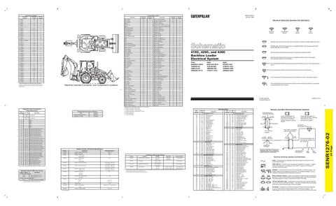
¹ The connectors shown in this chart are harness to harness connectors. Connectors that join a harness to a component are generally located at or near the component. See the Component Location Chart.
Machine Harness Connector and Component Locations
Resistor - Air Conditioning
K-18
A
Switch - Rear Wiper
D-12
E
Resistor - Heater
E-16
A
Switch - Refrigerant
J-16
23
Resistor - Powershift
I-9
B
Switch - Return To Dig
L-16
13
Sender - Converter Temperature
G-3,I-5
6
Switch - Rear Steer
K-8
B
Sender - Coolant Temperature
E-3,I-4
12
Switch - Seat
K-9
F
Sender - Fuel Level
G-4,H-5
13
Switch - Start
D-14
A A
Sensor - Rear Steer Position
J-9
7
Switch - Start Aid
D-14
Sensor - RTD
L-17
14
Switch - Thermostat
J-18
9
Sensor - Speed
H-13
G
Switch - Transmission Neutral
D-4
24
Solenoid - Air Conditioning Clutch
J-16
15
Switch - Transmission Neutral
I-5
24
Solenoid - Aux Detent
A-6
16
Switch - Transmission Neutral
L-8
24
Solenoid - Backhoe Shutoff Valve
H-11
1
Switch - Transmission Neutral Lock
D-6
B
A-4
16
Switch - Turn Signal
E-5
B
Solenoid - Bucket Position
Diagnostic Code Conversion for Power Shift Control Code Flashed 11 12
CID - FMI No ACTIVE Faults
Title
Not applicable.
Form No.
Powershift Transmission Control
SENR1274
Starting Motor: 143-0539
SENR3828
Solenoid - Circle Steer
L-9
7
Switch - OROPS Rear Floods
K-1
C
Solenoid - Cold Start Advance
H-5
12
Tachometer
B-17
A
Machine locations are repeated for components located close together A = Operator Compartment - Right Console B = Operator Compartment - Front Console C = Operator Compartment - Overhead Console D = Operator Compartment - Steering Column Top Panel E = Operator Compartment F = Inside Seat Assembly G = Under Cab Floorplate
Related Electrical Service Manuals
Description
-
416C
14
-
426C
15
-
428C
16
-
436C
17
-
438C
18
-
BHL
31
641 - 05
Forward High Solenoid Open Circuit
32
642 - 05
Reverse Solenoid Open Circuit
33
643 - 05
Forward Low Solenoid Open Circuit
34
644 - 05
Speed 1 Solenoid Open Circuit
35
645 - 05
Speed 2 Solenoid Open Circuit
36
646 - 05
Speed 3 Solenoid Open Circuit
38
683 - 05
Parking Brake Alarm Open Circuit
41
641 - 06
Forward High Solenoid Short to Ground
42
642 - 06
Reverse Solenoid Short to Ground
43
643 - 06
Forward Low Solenoid Short to Ground
44
644 - 06
Speed 1 Solenoid Short to Ground
45
645 - 06
Speed 2 Solenoid Short to Ground
46
646 - 06
Speed 3 Solenoid Short to Ground
48
683 - 06
Parking Brake Alarm Short to Ground
51
641 - 03
Forward High Solenoid Short to Battery
52
642 - 03
Reverse Solenoid Short to Battery
53
643 - 03
Forward Low Solenoid Short to Battery
Part No.
Component
54
644 - 03
Speed 1 Solenoid Short to Battery
3E-1908
55
645 - 03
Speed 2 Solenoid Short to Battery
3E-6184
Resistor - Powershift
56
646 - 03
Speed 3 Solenoid Short to Battery
3E-8620
Solenoid - Auxiliary Detent
3.5 ± .15 100 ± 5
683 - 03
Parking Brake Alarm Short to Battery
62
191 - 02
Transmission Speed Sensor
63
668 - 02
Invalid Shift Lever Input
Shutoff
64
168 - 00
Battery Voltage Above Normal
Valve Group A
65
168 - 01
Battery Voltage Below Normal
66
650 - 02
Invalid Harness Code Input
73
590 - 02
Trans Configuration Incorrect
3E-8622
4W-9972
Solenoid - Sideshift Lock
Sender - Converter Temperature
Sender - Coolant Temperature
Detected Faults For Shift Lever Control CID No. / FMI No.
113-5320
Description
FMI 01
System voltage above normal. System voltage below normal.
Loader Lock RH
110°C (230°F) - 72 to 82 8.5
Right Steer 121-4036
Solenoid - First and Second Gear
10.5
Front Drive
CID 668 - Transmission Shift Lever: FMI 12 Shift lever bad device or component. Note: The CID-FMI diagnostic codes for the Shift Lever Control are accessed by the ET or ECAP service tool only.
54°C (130°F) - 560 to 716
Left Steer
CID 168 - Electrical System: FMI 00
Solenoid - Loader Lock LH
Solenoid - Circle Steer
128-2875
Sender - Fuel Level Empty:
240 - 260
Full:
27.5 - 39.5
129-4531
Solenoid - Lock
134-2885
Resistor - Air Conditioner
10.5 Overall 1.0 ± 0.1 Tap 0.5 ± 0.05
Heater 138-1976 ¹ At room temperature.
Solenoid - Hydraulic Shutoff
6T-2665
Engine Coolant Temperature
9X-5446
Thermostat
114-5333
Refrigerant Pressure (AC)
54°C (130°F) - 560 to 716 110°C (230°F) - 72 to 82
8C-5541
Function
54°C (130°F) - 560 to 716 110°C (230°F) - 72 to 82
7N-8532
Off Machine Switch Specification Part No.
10.5
8.15 ± 0.6
416C, 426C, and 436C Backhoe Loader Electrical System 416C: 4ZN5635-16043 1AR649-UP 1KR416-UP 1WR2947-8115
128-5091
AWS Pressure
Actuate
Deactuate
Contact Position
107.2 ± 2.8ºC
93ºC MIN
Normally Open
(225 ± 5ºF)
(196ºF MIN)
.25Nm to .43Nm
--
(.19 lb ft to .32 lb ft)
--
275 to 1750 kpa¹
--
(40 to 255 psi)
--
Normally Open
Normally Open²
551 kPa
344 kPa ± 20 kPa
A-C Normally Closed
(36.3 psi)
(49.9 psi ± 2.9 psi)
A-B Normally Open
¹ A hysteresis band exists: with increasing pressure the closed condition can be maintained up to 2800 kpa (405 psi), with decreasing pressure the closed condition can be maintained down to 170 kpa (25 psi). ² Contact position at the contacts of the harness connector.
426C: 6XN1245-3615 1CR364-863 1MR456-955 1YR517-1516
Normally closed switch that will open with an increase of a specific condition.
Normally closed switch that is open due to an applied condition, and will close again with a specific decrease in that condition.
436C: 8TN391-924 1FR416-1415 1PR598-1598 2AR604-1603
The circle indicates that the component has screw terminals and a wire can be disconnected from it.
No circle indicates that the wire cannot be disconnected from the component.
This indicates that the component has a wire connected to it that is connected to ground.
This indicates that the component does not have a wire connected to ground. It is grounded by being fastened to the machine.
Printed in U.S.A.
© 1998 Caterpillar All Rights Reserved
200 201 202 217 218 265 270 276 277 278 279 280 281
32.1
Bucket Position
58
Normally open switch that is closed due to an applied condition, and will open again with a specific decrease in that condition.
101 102 104 105 110 111 112 113 115 116 117 118 119 121 122 123 124 128 130 136 140 143 144 157 161 170 194 197 198
Resistance (Ohms)¹
Solenoid - A/C Compressor Clutch
Flow Symbol
Level Symbol
Normally open switch that will close with an increase of a specific condition (temp-press-etc.).
Harness And Wire Electrical Schematic Symbols
Wire Description
Resistor, Sender, and Solenoid Specifications
Temperature Symbol
Pressure Symbol
Wire Number
No INACTIVE Not applicable. Faults
13
T
14
A
CONN 21
CONN 23
Electrical Schematic Symbols And Definitions
303 304 306 307 308 309 310 321 322 334 367 405 406 419 429 441 443 447 450 483 500 501 502 503 504 505 506 507 508 509 511 512 513 515 516
Wire Color
Description
Power Distribution Circuits RD Bat (+) RD Running Lamp Pwr YL Acc Rly Output RD Key Sw Pwr RD Horn Pwr YL Acc Bat Pwr PU Main Power Rly Output OR Opr Mon Panel Pwr RD Acc Socket Pwr BR Std Rear Flood Pwr YL Aux Rear Flood Pwr GY Front Wiper Pwr PK Rear Wiper Pwr YL Back Alarm Pwr BU Heater Pwr WH XMSN Ctrl Pwr GN A/C Pwr PK Bucket Position Pwr GN Radio Pwr GN Suppl Steer Pwr BU Blower Pwr BR AWD Pwr GN Beacon Pwr YL Aux Front Flood Pwr RD Flasher Pwr RD Radio Memory Pwr GN Cab Bat Pwr GN Cab Relay Output PK A/C Relay Output Ground Circuits BK Main Chassis BK Operator Monitor return BK XMSN Ctrl Gnd BK Start relay return BK Drop valve relay return BK Loader Lock Gnd BK Loader Lock Gnd BK Pshift Ctrl Harn Code 0 BK Pshift Ctrl Harn Code 1 BK Pshift Ctrl Harn Code 2 BK Pshift Ctrl Harn Code 3 BK Pshift Ctrl Harn Code 4 BK Pshift Ctrl Harn Code 5 Basic Machine Circuits BR Key SW ACC Position WH Start Relay Output GN Starter Relay Coil OR Key Sw Start Position YL Key Sw Run Position GY Alternator Regulator Term. PU Start Aid Sol BR Backup Alarm GY Forward Horn BU Cold Start Adv Sol BU Rear Horn Monitoring Circuits GY Opr Mon Oil Press. (Low Setting) PU Opr Mon Coolant Temp YL Opr Mon Parking Brake YL AWS Position Gage OR Eng Coolant Temp Gage YL Converter Temp Gage PK Fuel Level Gage YL Tach Sender (+) BR Opr Mon Brake Fluid Level Accessory Circuits BR Wiper - Front (Park) GN Wiper - Front (Low) OR Wiper - Front (HI) BR Wiper - Rear (Park) YL Wiper - Rear (Low) BU Wiper - Rear (HI) PU Washer - Front WH Washer - Rear PU Radio Speaker - Left WH Radio Speaker - Left (Common) BR Radio Speaker - Right GN Radio Speaker - Right (Common) OR A/C Compressor/Refrigerant Pressure SW GY Blower Motor (HI) GN Blower Motor (Medium)
Wire Number 517 520 521 522 536 537 552 568 578 C558 C559 C593 C594 C595 602 603 604 605 606 607 608 610 611 614 617 618 619 620 627 630 634 710 752 754 755 762 766 779 C720 E764 F765 G726 G742 G743 G789 G795 G796 G797 G798 H767 H768 H769 H770 H771 H772 F871 F872 F873 F874 F877 922 923 944 945 975 991 C920 C993 L998 L999 M913 M968 N904 N905 N907 P909 R977 R978
Wire Color
Description
Accessory Circuits (cont'd) BU Blower Motor (Low) WH Opr A/C SW To Thermostat/Fuse YL A/C SW To Refrigerant SW WH A/C Clutch To Thermostat SW WH Hazard SW To Turn SW GN Turn Signal SW To Flasher WH Four Wheel Drive Sol GN Park Brake Alarm Sig BU Washer - Aux YL Front Wiper Switch Jumper YL Rear Wiper Switch Jumper OR Power Seat Relay Control YL Power Seat Motor GN Power Seat Heater Lighting Circuits RD Dome Lamp Pwr PK Rotary Beacon OR Stop Lamp YL Turn Lamp - Left GY Turn Lamp - Right PK Flood Lamp - Front GN Flood Lamp - Rear OR Head Lamp Basic PU Head Lamp Hi PU Park/Tail/Dash/Lamp BR Tail/Position Lamp - Left YL Tail/Position Lamp - Right GN Headlamp low WH Flood Lamp - Front (Attach) YL Fog Lamp GY Flood Lamp Rear (Attach) WH Head Lamp SW To Work/Head Lamp Jumper Control Circuits GN XMSN Speed Pickup Signal YL XMSN Shift Sol 1st and 2nd Gear BU XMSN Shift Sol 3rd Gear OR XMSN Shift Sol 4th Gear YL Bucket Positioner Sol GN XMSN Disconnect SW WH Coupler Engage Sol BU XMSN Neutral Lock Sig OR AWS Circle Steer/Lock Sol BR Park Brake SW To Relay GY AWS Shut Off Sol GN AWS Relay Coil to Diode OR AWS Relay Coil to Diode BR AWS Mode SW To Press SW OR AWS Mode SW To Rear Steer SW Pwr YL AWS Mode SW To Rear Steer SW Gnd BU AWS Left Steer Relay Gnd PU AWS Right Steer Relay Gnd BR AWS Circle Steer/Lock Sol Gnd BR AWS Left Steer Sol Gnd BR AWS Right Steer Sol Gnd BR AWS Shut Off Sol Gnd BR Side Shift Lock Sol YL Backhoe Shutoff Sol PU AWS Left Steer Sol BU AWS Right Steer Sol YL Relay Contact To Diode As PK AWS Left Steer Relay Ctrl WH AWS Right Steer Relay Ctrl BR FWD Solenoid Rtn GY REV Sol Rtn OR Data Link + (CAT) BR Data Link - (CAT) WH Powershift - Sol Return WH XMSN Neut SW GY Diagnostic Indicator - Powershift WH Shuttle Ctrl Pwr OR Aux Hyd Sol B GN Aux Hyd Sol C PU Diode to AWS Indicator Lamp BU Coupler Switch Interconnect PU Forward High Solenoid OR Forward Low Solenoid GN Reverse Low Solenoid PK Autoshift Disable BU Stabilizer leg sw YL Shuttle control jumper
Typical representation of a Sure-Seal connector. The plug and receptacle contain both pins and sockets.
Typical representation of a Deutsch connector. The plug contains all sockets and the receptacle contains all pins.
L-C12 * 3E-5179
AG-C4 * 111-7898
1 2
1 2
Part Numbers For Connector Assembly
1
Receptacle
Plug
Component Part Number
2 Wire, Cable, or Harness Assembly Identification
Pin or Socket Number
* C-C4* AG-C3 130-6795 130-6795 325-A135 PK-14 Pin
L-C12* 3E-5179
AG-C4* 111-7898
9X-1123
1
Harness identification code This example indicates wire 32 in harness "L'.
2
200-L32 BK-14
Socket
Single Wire Connector * Harness identification letter(s) and a serializing code. The "C" stands for connector and the number indicates which connector in the harness.
Circuit Number Identification
Wire Color
Wire Gauge
Electrical Schematic Symbols And Definitions FUSE - A component in an electrical circuit that will open the circuit if too much current flows through it. REED SWITCH - A switch whose contacts are controlled by a magnet. A magnet closes the contacts of a normally open reed switch; it opens the contacts of a normally closed reed switch.
T
SENDER - A component that is used with a temperature or pressure gauge. The sender measures the temperature or pressure. Its resistance changes to give an indication to the gauge of the temperature or pressure. RELAY (Magnetic Switch) - A relay is an electrical component that is activated by electricity. It has a coil that makes an electromagnet when current flows through it. The electromagnet can open or close the switch part of the relay. CIRCUIT BREAKER (C/B) - A component in an electrical circuit that will open the circuit if too much current flows through it. This does not destroy the circuit breaker and it can be reset to become part of the circuit again. SOLENOID - A solenoid is an electrical component that is activated by electricity. It has a coil that makes an electromagnet when current flows through it. The electromagnet can open or close a valve or move a piece of metal that can do work.
20 Page
CONN 1
Schematic Location
SENR1276-02
Machine Location
CONN 6
SENR1276-02 January 1998
Component Location
Schematic Location
325-L25 PK-14
Connector Location¹ Connector Number