FMI No.
Wire Number
Failure Mode Identifiers (FMI)
Wire Description
Wire Color
Description
Wire Number
Wire Color
Power Circuits
Failure Description
Description
SENR1275-03 December 2000
Accessory Circuits (cont'd)
0
Data valid but above normal operational range.
101
RD
Bat (+)
522
WH
A/C Clutch To Thermostat SW
1
Data valid but below normal operational range.
102
RD
Running Lamp Pwr
536
WH
Hazard SW To Turn SW
2
Data erratic, intermittent, or incorrect.
104
YL
Acc Rly Output
537
GN
Turn Signal SW To Flasher
3
Voltage above normal or shorted high.
4
Voltage below normal or shorted low.
105
RD
Key Sw Pwr
552
WH
Four Wheel Drive Sol
5
Current below normal or open circuit.
110
RD
Horn Pwr
568
GN
Park Brake Alarm Sig
6
Current above normal or grounded circuit.
111
YL
Acc Bat Pwr
571
OR
Powershift - Ride Control Relay
7
Mechanical system not responding properly.
112
PU
Main Power Rly Output
578
BU
Washer - Aux
8
Abnormal frequency, pulse width, or period.
113
OR
Opr Mon Panel Pwr
619
GN
Headlamp low
13 25 10 9
9
Abnormal update.
115
RD
Acc Socket Pwr
C558
YL
Front Wiper Switch Jumper
10
Abnormal rate of change.
11
Failure mode not identifiable.
116
BR
Std Rear Flood Pwr
C559
YL
Rear Wiper Switch Jumper
12
Bad device or component.
117
YL
Aux Rear Flood Pwr
C593
OR
Power Seat Relay Control
13
Out of calibration.
118
GY
Front Wiper Pwr
C594
YL
Power Seat Motor
14
Parameter failures.
119
PK
Rear Wiper Pwr
C595
GN
Power Seat Heater
15
Parameter failures.
121
YL
Back Alarm Pwr
16
Parameter not available.
122
BU
Heater Pwr
602
RD
Dome Lamp Pwr
17
Module not responding.
18
Sensor supply fault.
123
WH
XMSN Ctrl Pwr
603
PK
Rotary Beacon
19
Condition not met.
124
GN
A/C Pwr
604
OR
Stop Lamp
20
Parameter failures.
128
PK
Bucket Position Pwr
605
YL
Turn Lamp - Left
130
GN
Radio Pwr
606
GY
Turn Lamp - Right
136
GN
Suppl Steer Pwr
607
PK
Flood Lamp - Front
9 10
The FMI is a diagnostic code that indicates what type of failure has occurred.
140
Component Identifiers (CID¹) Module Identifier (MID²) Power Train Control (MID No. 081)
CID
Component
0041
+ 8 Volt Sensor Supply
0138
Reduced Rimpull Selection Switch
0143
Neutralizer Press Switch
0144
Backup Alarm Relay
0168
System Voltage
0190 0191
16 7
E F
1 A
Blower Pwr
608
GN
Flood Lamp - Rear
143
BR
AWD Pwr
610
OR
Head Lamp Basic
144
GN
Beacon Pwr
611
PU
Head Lamp Hi
157
YL
Aux Front Flood Pwr
614
PU
Park/Tail/Dash/Lamp
161
RD
Flasher Pwr
617
BR
Tail/Position Lamp - Left
170
RD
Radio Memory Pwr
618
YL
Tail/Position Lamp - Right
194
GN
Cab Bat Pwr
620
WH
Flood Lamp - Front (Attach)
197
GN
Cab Relay Output
627
YL
Fog Lamp
198
PK
A/C Relay Output
630
GY
Flood Lamp Rear (Attach)
634
WH
Head Lamp SW To Work/Head Lamp Jumper
GN
XMSN Speed Pickup Signal
Ground Circuits
D
B
2
19
8
14
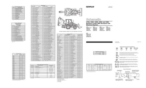
416C, 426C, 428C, 436C and 438C Backhoe Loader With European Cab Electrical System
21 19 18
A
26 F 1
7
25 20
Control Circuits
Main Chassis Operator Monitor return
710
202
BK
XMSN Ctrl Gnd
752
YL
XMSN Shift Sol 1st and 2nd Gear
Eng Speed Sensor Signal
217
BK
Start relay return
754
BU
XMSN Shift Sol 3rd Gear
Transmission Speed Sensor Signal
218
BK
Drop valve relay return
755
OR
XMSN Shift Sol 4th Gear
0248
Data Link
265
BK
Loader Lock Gnd
762
YL
Bucket Positioner Sol
0254
Electronic Control Module (ECM)
0444
Start Relay
270
BK
Loader Lock Gnd
766
GN
XMSN Disconnect SW
0590
Eng Electronic Control Module
276
BK
Pshift Ctrl Harn Code 0
779
WH
Coupler Engage Sol
0603
Impeller Clutch Press Sensor
277
BK
Pshift Ctrl Harn Code 1
C720
BU
XMSN Neutral Lock Sig
0623
Direction Switch
278
BK
Pshift Ctrl Harn Code 2
E701
PK
Ride Control
0626
Steering/Transmission Lock Switch
279
BK
Pshift Ctrl Harn Code 3
E702
OR
Ride Control SW
0627
Parking Brake Press Switch
280
BK
Pshift Ctrl Harn Code 4
E764
OR
AWS Circle Steer/Lock Sol
0628
Quick-Shift Switch
281
BK
Pshift Ctrl Harn Code 5
F738
WH
Loader Rod End Pressure SW
0650
Harness Code
Basic Machine Circuits
F748
WH
Powershift - Ride Control Manual
0672
Torque Converter Output Speed Sensor
F765
BR
Park Brake SW To Relay
F-5
B
Torque Converter Impeller Clutch Solenoid
Key SW ACC Position
Action - Lightbar
0678 0679
Torque Converter Lockup Clutch Solenoid
AWS Shut Off Sol
Alarm - Backup
D-18
1
0826
Torque Converter Oil Temperature Sensor
AWS Relay Coil to Diode
Alarm - Light Bar
D-16
1401
Transmission Clutch 1 Solenoid Valve (Reverse)
AWS Relay Coil to Diode
Alternator
1402
Transmission Clutch 2 Solenoid Valve (Forward)
308
1403
Transmission Clutch 3 Solenoid Valve (Speed) 3
309
GY
Alternator Regulator Term.
G795
1404
Transmission Clutch 4 Solenoid Valve (Speed) 4
310
PU
Start Aid Sol
G796
1405
Transmission Clutch 5 Solenoid Valve (Speed) 5
321
BR
Backup Alarm
322
GY
334 367
3
G 16
13
11
6 24 4
5
12
14
17 22 2
8
15 23
416C: 5YN3800-15147 1BR649-UP 1LR416-UP 1XR684-2183
Solenoid - Cold Start Advance
H-5
12
Solenoid - Engine Shutdown
G-3
17
A
Solenoid - First and Second Gear
H-13
G
E-3
2
Solenoid - Front Drive
F-3, I-5
G
AWS Mode SW To Press SW
Assembly - Fan
E-17
3
Solenoid - Fuel Shutdown
I-4
7
OR
AWS Mode SW To Rear Steer SW Pwr
Batteries
C-3
4
Solenoid - Group A (Forward High and Low)
I-13
G
YL
AWS Mode SW To Rear Steer SW Gnd
Breaker - Running Lamp
F-10
A
Solenoid - Group B (Third & Fourth Gear)
I-13
G
G797
BU
AWS Left Steer Relay Gnd
Coil - Forward Solenoid
G-3
G
Solenoid - Hydraulic Shutoff
B-18
1
Forward Horn
G798
PU
AWS Right Steer Relay Gnd
Coil - Reverse Solenoid
F-3
G
Solenoid - Left Steer
K-9
7
BU
Cold Start Adv Sol
H767
BR
AWS Circle Steer/Lock Sol Gnd
Coil - Thermostart
J-4, E-3
5
Solenoid - Loader Lock LH
I-7
18
BU
Rear Horn
H768
BR
AWS Left Steer Sol Gnd
Control - Powershift
L-12
4
Solenoid - Loader Lock RH
I-7
19
H769
BR
AWS Right Steer Sol Gnd
Control - Shuttle
E-8
D
Solenoid - Lock
L-9
7
K-13
D
Solenoid - Reverse
I-13
G
K-9
7
WH GN OR YL
Start Relay Output Starter Relay Coil Key Sw Start Position Key Sw Run Position
G726 G742 G743 G789
GY GN OR BR
Component
Schematic Location
Component Location
Machine Location
BR
Machine Location
Component
405
GY
Opr Mon Oil Press. (Low Setting)
H770
BR
AWS Shut Off Sol Gnd
Control - Shuttle (Powershift)
406
PU
Opr Mon Coolant Temp
H771
BR
Side Shift Lock Sol
Flasher
F-10
B
Solenoid - Right Steer
419
YL
Opr Mon Parking Brake
H772
YL
Backhoe Shutoff Sol
Fuses
F-11
D
Solenoid - Shutoff
K-9
7
429
YL
AWS Position Gage
F871
PU
AWS Left Steer Sol
Fuses
F-14
C
Solenoid - Side Shift Lock
B-18
1
441
OR
Eng Coolant Temp Gage
F872
BU
AWS Right Steer Sol
Fuses
K-3
C
Solenoid - Valve Group A
F-1
8
443
YL
Converter Temp Gage
F873
YL
Relay Contact To Diode As
Gauge - AWS Position
L-5
B
Switch - Air Conditioner Blower
K-16
A
447
PK
Fuel Level Gage
F874
PK
AWS Left Steer Relay Ctrl
Gauge - Converter Temperature
B-15
A
Switch - Aux Coupler
C-6
B
450
YL
Tach Sender (+)
F877
WH
AWS Right Steer Relay Ctrl
Gauge - Coolant Temperature
B-16
A
Switch - Aux Rear Flood
G-13
C
FWD Solenoid Rtn
Gauge - Fuel Level
B-16
A
Switch - AWD
E-6
B
G-3
6
Switch - AWS Mode Select
L-5
B
K-8
20
483
BR
Opr Mon Brake Fluid Level Accessory Circuits
922
BR
923
GY
REV Sol Rtn
Ground - Engine
OR
Data Link + (CAT)
Ground - Headliner
B-12
C
Switch - AWS Pressure
500
BR
Wiper - Front (Park)
944
501
GN
Wiper - Front (Low)
945
BR
Data Link
Ground - Platform
B-14
7
Switch - Backhoe Shutoff
D-17
A
502
OR
Wiper - Front (HI)
975
WH
Powershift - Sol Return
Ground - Steer Column
E-10
3
Switch - Beacon
E-12
C
503
BR
Wiper - Rear (Park)
976
OR
Ride Control Relay
Horn - Forward
B-3
8
Switch - Brake A
D-9
E
D-18
1
Switch - Brake B
D-9
E
B
Switch - Brake Fluid Level
C-4
21
- (CAT)
504
YL
Wiper - Rear (Low)
991
WH
XMSN Neut SW
Horn - Rear
505
BU
Wiper - Rear (HI)
C920
GY
Diagnostic Indicator - Powershift
Horn - Stabilizer Leg
H-8
506
PU
Washer - Front
C993
WH
Shuttle Ctrl Pwr
Junction - Power
D-9
3
Switch - Cold Start Temperature
L-5
B
Switch - Coolant Temperature
WH
Washer - Rear
L998
OR
Aux Hyd Sol B
Lamp - Indicator
Aux Hyd Sol C
LED - Service
L-14
A
Switch - Coupler
D-6
B
CONN 1
J-18
9
509
WH
Radio Speaker - Left (Common)
M913
PU
Diode to AWS Indicator Lamp
Meter - Service
D-14
A
Switch - Coupler Detent
A-15
A
CONN 2
J-17
9
M968
BU
Coupler Switch Interconnect
9
Switch - Dip Beam
F-6
B
A
Radio Speaker - Right
K-18
L-17
BR
Motor - Air Conditioning Blower
CONN 3
511
Radio Speaker - Right (Common)
N904
PU
Forward High Solenoid
3
Switch - Engine Oil Pressure
F-3, H-4
22
9
GN
E-17
L-17
512
Motor - Fan Assembly
CONN 4 CONN 5
H-7, H-8, J-15
A
513
OR
A/C Compressor/Refrigerant Pressure SW
N905
OR
Forward Low Solenoid
Motor - Front Washer
C-3
21
Switch - Fog Lamp
K-17
A
G-5
C
Switch - Front Roading
G-12
C
L-15
4
515
GY
Blower Motor (HI)
N907
GN
Reverse Low Solenoid
B-14
A
516
GN
Blower Motor (Medium)
P909
PK
Autoshift Disable
Motor - Heater Blower
D-17
A
Switch - Front Roading OROPS
CONN 8
B-14, L-9, L-10
A
517
Stabilizer leg sw
Motor - Rear Washer
C-3
21
Switch - Front Wiper
CONN 9
C-14, I-3
A
520
WH
Opr A/C SW To Thermostat/Fuse
Shuttle control jumper
Motor - Rear Wiper
E-17
10
Switch - Hazard
CONN 10
C-14, I-3
A
A/C SW To Refrigerant SW
11
A
YL
D-3
C-14
521
Motor - Starter
CONN 11 CONN 12
I-14
G
Power Port
D-14
A
CONN 13
K-14
25
Radio
H-17
CONN 14
K-14
25
F-9
L-14
4
CONN 16
B-13, K-2
CONN 17
C-13, K-2
CONN 18
J-13
3
CONN 19
J-13
3
CONN 20
D-11, J-3
3
3E-1908
Solenoid: A/C Clutch
17.6 ± 0.6
CONN 21
D-11, J-3
3
3E-6184
Resistor: Powershift
100 ± 5
CONN 22
B-10, K-2
C
3E-8620
Solenoid: Aux Dent, Bucket Pos
32.1
CONN 23
D-10, J-2
3
CONN 24
D-10, J-2
3
3E-8622
Solenoid: Sideshift Lock, Shutoff, Valve Group A
10.5
CONN 27
I-8
1
CONN 28
F-7
B
CONN 29
F-7, J-1
B
CONN 30
F-7, J-1
B
CONN 31
J-7
3
CONN 32
K-7
7
CONN 33
K-7
3
CONN 34
K-7
3
CONN 35
D-5, I-1, I-6
6
CONN 36
D-5, I-1, I-6
6
CONN 37
D-5, I-1, I-6
6
CONN 38
B-5
3
CONN 39
B-5, H-1
6
CONN 40
K-5
3
CONN 41
K-5
3
CONN 42
C-4
G
CONN 43
B-3
6
CONN 44
F-1
8
CONN 15
Data Link
R977 R978
BU YL
Relay - Accessory
L-1
C
E-12
C
F-6
B
Switch - Head Flood Atch
G-13
C
Switch - Head to Floodlights
F-12
C
C
Switch - Heater
A-14
B
D
Switch - Horn
C-6
B
Relay - Air Conditioning
F-9
B
Switch - Loader Lock
I-7
1
C
Relay - Cab
E-9
D
Switch - Loader Transmission Neutralizer
D-5
E
C
Relay - Left Steer
D-4
B
Switch - OROPS Beacon
K-1
C
CONN 45 F-1 8 The connectors shown in this chart are harness to harness connectors. Connectors that join a harness to a component are generally located at or near the component. See the Component Location chart.
Resistor, Sender, and Solenoid Specifications Component Description
Part No.
4W-9972 7N-8532 8C-5541
Sender: Converter Temp Sender: Coolant Temp Solenoid: LH/RH Loader Lock
Resistance (Ohms)¹
560 to 716 at 54°C (130°F) 72 to 82 at 110°C (230°F) 560 to 716 at 54°C (130°F) 72 to 82 at 110°C (230°F) 560 to 716 at 54°C (130°F) 72 to 82 at 110°C (230°F)
113-5320
Solenoid: Right/Left Lock
8.5
121-4036
Solenoid: Front Drive
10.5
126-3707
Solenoid: Ride Control
2.8 ± 0.3
Fuel Level 128-2875
Sender: Empty:
240 to 260
Full:
27.5 to 39.5
A/C
Overall: 1.0 ± 0.1
134-2885
Resistor:
Heater
Tap: 0.5 ± 0.05
138-1976
Solenoid: Hydraulic Shutoff
8.15 ± 0.6
¹ At room temperature.
Relay - Loader Lock
I-9
A
Switch - OROPS Head To Flood
K-1
C
Relay - Main
F-9
D
Switch - OROPS Rear Floods
K-1
C
Relay - Park Brake
K-15
A
Switch - Overdrive Disable
J-11
B
Relay - Right Steer
K-4
B
Switch - Park Brake
B-8
A
Relay - Seat
L-10
F
Switch - Rear Floods
F-12
C
Relay - Shutoff
J-4
B
Switch - Rear Horn
B-17
A
Relay - Start
E-9
D
Switch - Rear Steer
K-8
B
Relay - Stabilizer Leg
H-8
E
Switch - Rear Wiper
D-13
E
Resistor - Air Conditioning
K-17
A
Switch - Refrigerant
J-16
23
Resistor - Heater
E-16
A
Switch - Return to Dig
L-16
13
Resistor - Powershift
K-10
B
Switch - Seat
K-10
F
Sender - Converter Temperature
G-3, I-5
6
Switch - Side Shift
D-16
A
Sender - Coolant Temperature
E-3, I-4
12
Switch - Stabilizer Leg
B-18
26
Sender - Fuel Level
G-4, H-5
13
Switch - Start
D-14
A
J-9
7
Switch - Start Aid
D-14
A
Sensor - RTD
L-18
14
Switch - Thermostat
Sensor - Speed
H-13
G
Switch - Transmission Neutral
Solenoid - Air Conditioning Clutch
J-17
15
Solenoid - Aux Detent
A-5
Solenoid - Bucket Position Solenoid - Circle Steer
Sensor - Rear Steer Position
J-18
9
D-4, I-5, K-8
24
Switch - Transmission Neutral Lock
D-6
B
16
Switch - Turn Signal
F-5
B
A-4
16
Switch - Washers
C-13
C
L-9
7
Tachometer
B-16
A
Machine locations are repeated for components located close together. A = Operator Compartment - Right Console B = Operator Compartment - Front Console C = Operator Compartment - Overhead Console D = Operator Compartment - Steering Column Top Panel E = Operator Compartment F = Inside Seat Assembly G = Under Cab Floorplate
Title
Form Number Alternator:
SENR7508 SENR3828
GN
Circuit Breaker Symbol
Flow Symbol
Level Symbol
Temperature Symbol
Related Electrical Service Manuals
SENR1274
L999
CONN 7
Pressure Symbol
Starter:
Radio Speaker - Left
CONN 6
T
Power Shift Transmission Control:
PU
Motor - Front Wiper
Electrical Schematic Symbols And Definitions
12
508
Printed in U.S.A.
© 2000 Caterpillar All Rights Reserved
12
Machine Location
Blower Motor (Low)
436C: 9JN384-883 1GR416-915 1RR498-997 2BR411-910
438C: 9KN561-1060 1JR607-1106 1TR783-1283 2DR1050-2716
H-4
Schematic Location
BU
428C: 8RN1629-4088 1HR403-UP 1SR423-UP 2CR4428-16211
F-3, H-4
507
Connector Number
426C: 7WN439-938 1ER364-863 1NR454-953 1ZR426-925
MACHINE HARNESS CONNECTOR AND COMPONENT LOCATIONS
Schematic Location
Monitoring Circuits
Connector Location
12
11 5
E
BK
¹ The CID is a diagnostic code that indicates which component is faulty. ² The MID is a diagnostic code that indicates which electronic control module diagnosed the fault.
23
C
BK
307
15
17
4
201
306
6
26
200
304
G
22
Lighting Circuits
BU
303
20
18 C 24 21 3 D B
Normally open switch that will close with an increase of a specific condition (temp-press-etc.). The circle indicates that the component has screw terminals and a wire can be disconnected from it. Normally closed switch that will open with an increase of a specific condition. No circle indicates that the wire cannot be disconnected from the component. This indicates that the component has a wire connected to it that is connected to ground.
This indicates that the component does not have a wire connected to ground. It is grounded by being fastened to the machine. Reed Switch - A switch whose contacts are controlled by a magnet. A magnet closes the contacts of a normally open reed switch; it opens the contacts of a normally closed reed switch. Sender - A component that is used with a temperature or pressure gauge. The sender measures the temperature or pressure. Its resistance changes to give an indication to the gauge of the temperature or pressure.
T
Relay (Magnetic Switch) - A relay is an electrical component that is activated by electricity. It has a coil that makes an electromagnet when current flows through it. The electromagnet can open or close the switch part of the relay.
Off Machine Switch Specification Part No. 6T-2665 9X-5446
Function Engine Coolant Temperature Thermostat
114-5333
Refrigerant Pressure
128-5091
AWS Pressure
Actuate
Deactuate
Contact Position
107.2 ± 2.8ºC
93ºC MIN
Normally
(225 ± 5ºF)
(196ºF MIN)
Open
.25Nm to .43Nm
--
Normally
(.19 lb ft to .32 lb ft)
--
Open
275 to 1750 kpa¹
--
Normally ²
(40 to 255 psi)
--
Open
551 kPa
344 kPa ± 20 kPa
A-C Normally Closed
(36.3 psi)
(49.9 psi ± 2.9 psi)
A-B Normally Open
Solenoid - A solenoid is an electrical component that is activated by electricity. It has a coil that makes an electromagnet when current flows through it. The electromagnet can open or close a valve or move a piece of metal that can do work.
Harness And Wire Symbols Harness identification code This example indicates wire 135 in harness "AG".
¹ A hysteresis band exists: with increasing pressure the closed condition can be maintained up to 2800 kpa (405 psi), with decreasing pressure the closed condition can be maintained down to 170 kpa (25 psi). ² Contact position at the contacts of the harness connector.
* * AG-C3 C-C4 130-6795 130-6795 325-A135 PK-14 Socket
Pin
Single Wire Connector
1 2
Wire Color
Ground Circuit Connection Number Identification Typical representation of a Deutsch connector. The plug contains all sockets and the receptacle contains all pins.
* Harness identification letter(s) and a serializing code. The "C" stands for connector and the number indicates which connector in the harness.
Wire, Cable, or Harness Assembly Identification Part Number For L-C12* AG-C4* Connector Assembly 3E-5179 111-7898 325-A135 PK-14 1 Wire Gauge
Receptacle Plug
2
200-L32 BK-14 Pin or Socket Number
1 2
Fuse
Typical representation of a Sure-Seal connector. The plug and receptacle contain both pins and sockets.
105-9344 Component Part Number