SEE DETAIL A
Y902-AC75
101-AC3
Y903-AC1
202-AC18
Y908-AC66 Y909-AC59 Y910-AC42 Y911-AC61
CB1-1-SJ1 229-SJ5
Y912-AC55 Y913-AC54
200-AC2
CR2-12-SJ3
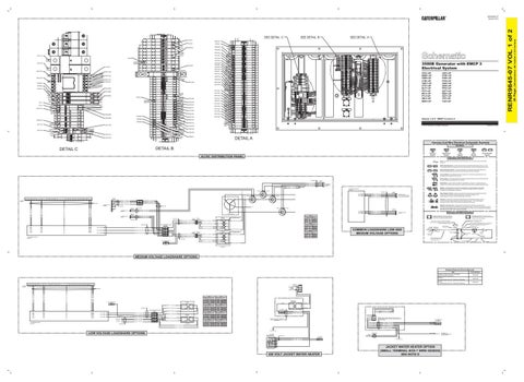
3500B Generator with EMCP 3 Electrical System
Y914-AC49 Y915-AC57
CB1-2-SJ2 101-AC15
Y916-AC53
CR2-11-SJ8
F705-AC56 F408-AC71
CPA1-UP BMB1-UP CNB1-UP CTB1-UP CMC1-UP CTC1-UP BLF1-UP PTF1-UP BPJ1-UP PTJ1-UP SBJ1-UP BRK1-UP
G487-AC51 CR2-21-SJ6
G488-AC45
CR2-22-SJ4 G490-AC58
CR2-31-SJ7 F709-AC68
R955-AC69
E565-AC60
AC-PMG-C
F702-AC52
AC-PMG-B N704-GEN9
AC-PMG-A
N713-AC21
N703-GEN6
N714-AC20 N752-AC22
N702-GEN5 229-SJ5
J904-AC23
F407-AC62
J905-AC24 AC-F1
F405-AC76
AC-F2
F406-AC73
LEK1-UP PTM1-UP FDN1-UP PTN1-UP GAR1-UP GZS1-UP PPS1-UP GZT1-UP BGX1-UP GZY1-UP 1FZ1-UP 1GZ1-UP
N716-AC25 N720-AC26 995-AC72
CR2-12-SJ3
N705-GEN7 Y794-RE30 N706-GEN8
Y795-RE32
CR2-22-SJ4
N717-AC29
P738-AC50
N715-AC30
R951-AC48
N718-AC28
Volume 1 of 2: EMCP 3.2 and 3.3
R952-AC46
Y796-RE34 CB1-1-SJ1
N719-AC27
P737-AC40
R953-AC47
CR2-11-SJ8
© 2012 Caterpillar, All Rights Reserved
Y794-AC33
Printed in U.S.A.
Y795-AC39 CB1-2-SJ2 Y796-AC36 CR2-31-SJ7 D998-AC1
CR2-21-SJ6
DETAIL A Harness And Wire Electrical Schematic Symbols Symbols
DETAIL B
DETAIL C
T
Pressure Symbol
AC/DC DISTRIBUTION PANEL
Temperature Symbol
Level Symbol
Circuit Breaker Symbol
Flow Symbol
Symbols and Definitions Fuse: A component in an electrical circuit that will open the circuit if too much current flows through it. Switch (Normally Open): A switch that will close at a specified point (temp, press, etc.). The circle indicates that the component has screw terminals and a wire can be disconnected from it. Switch (Normally Closed): A switch that will open at a specified point (temp, press, etc.). No circle indicates that the wire cannot be disconnected from the component. Ground (Wired): This indicates that the component is connected to a grounded wire. The grounded wire is fastened to the machine. Ground (Case): This indicates that the component does not have a wire connected to ground. It is grounded by being fastened to the machine.
252-7355
MP-C3 1028804
MP-S1
1 2 3 4
CL-16-UL CL-16-UL CL-16-UL CL-16-UL
Reed Switch: A switch whose contacts are controlled by a magnet. A magnet closes the contacts of a normally open reed switch; it opens the contacts of a normally closed reed switch.
TO EMCP3 HARNESS W-C3
23 1
F453-MP5 CL-16-UL F453-MP6 CL-16-UL F453-MP7 CL-16-UL
F488-MP1 F450-MP2 F452-MP3 F453-MP4
LOADSHARE MODULE 309-1583 PT1-T1
MP-T1X1
1 2 3 4 5 CONNECTS TO 6 W-C36 7 8 9 10 11 12
SP-1-ML6 GY-18-UL SP-2-ML7 GY-18-UL SP-3-ML8 GY-18-UL
101-ML1 GY-14-UL 202-ML2 GY-14-UL
D998-ML3 GY-18-UL F702-ML4 GY-18-UL
200-ML5 GN YL-18-UL
252-7435
F409-S4 GY-16-UL 324-5608
ML-T5 LSM26 ML-T6 LSM27 ML-T7 LSM28
F448-LC1 F450-LC2 F453-LC3 F453-LC4
1 2 3 4
GY-16-UL GY-16-UL GY-16-UL GY-16-UL
Relay (Magnetic Switch): A relay is an electrical component that is activated by electricity. It has a coil that makes an electromagnet when current flows through it. The electromagnet can open or close the switch part of the relay.
CONNECTS TO MP-C3 (MED VOLTAGE) CT-C3 (LOW VOLTAGE)
Solenoid: A solenoid is an electrical component that is activated by electricity. It has a coil that makes an electromagnet when current flows through it. The electromagnet can open or close a valve or move a piece of metal that can do work. Magnetic Latch Solenoid: A magnetic latch solenoid is an electrical component that is activated by electricity and held latched by a permanent magnet. It has two coils (latch and unlatch) that make electromagnet when current flows through them. It also has an internal switch that places the latch coil circuit open at the time the coil latches.
N MC-C2 3E3364 CONNECTS TO MA-C2
252-7354
1 2
F454-MC2 GY-16-UL F455-MC1 GY-16-UL
T3
CONNECTS TO MA-C3
1 2 3
E488-MG1 GY-16-UL E487-MG2 GY-16-UL E486-MG3 GY-16-UL
E486-MT1 GY-16-UL
MT-T2 LSM1
E487-MT2 GY-16-UL
MT-T3 LSM2
E488-MT3 GY-16-UL
MT-T1 LSM3
MP-T3X1
MP-T3X2 LC-C2 1552272 LC-T4 LSM5 LC-T5 LSM7 LC-T6 LSM9
GENERATOR
MG-C3 3E3370
252-7358 ML-T8-LSM GND
LC-T1 LSM4 LC-T2 LSM6 LC-T2 LSM8
MP-T2X2
252-7356
252-7446
ML-T3-LSM20 ML-T4-LSM19
MP-T2X1
LC-C1 1028804
E486-MV1 GY-18-UL E487-MV2 GY-18-UL E488-MV3 GY-18-UL 200-MV4 GN YL-16-UL
252-7353
ML-T1 LSM15 ML-T2-LSM16
T2
PT2-T2
T1 F4 F5 F6 GND V-TRM 10
E486-S1 GY-16-UL E487-S2 GY-16-UL E488-S3 GY-16-UL
MC-T2X2
PT2-T3
ML-C32 1338753
PT1-T2
20 21 50 42 34 52 65 62 63 64 17 66 67 8 9 16 22 23 18 31 1 51 24 29 30 39 41 47 49 57 59 60 61 48 2 3 4 5 6 7 11 14 15 25 26 27 28 32 33 35 36 37 38 40 43 44 45 46 53 54 55 56 58 68 69 70 10 12 13
S-C36 2259435
T
MP-T1X2 244-9643
MC-T2X1
Sender: A component that is used with a temperature or pressure gauge. The sender measures the temperature or pressure. Its resistance changes to give an indication to the gauge of the temperature or pressure.
MV LOADSHARE TERM MV TB1 2527357 22 22 22 24 24 24 20 20 20
MS-C1 PT-C1 1028804 1552272 1 E486-MS1 GY-18-UL 2 3 E487-MS2 GY-18-UL 4 200-MS3 GN YL-16-UL
ME-C2 PT-C2 1028804 1552272 1 E487-ME1 GY-18-UL 2 3 E488-ME2 GY-18-UL 4 200-ME3 GN YL-16-UL
LOADSHARE MODULE 309-1583
252-7359 DC TERM STRIP 2449603 GND GND
MV-PT1 2527445 X1
4160V BUS BAR WIRE PT# TERMINATION COLOR 1 T1 RED 1 T2 BLACK 2 T2 BLACK 2 T3 RED 3300V BUS BAR WIRE PT# TERMINATION COLOR 1 T1 YELLOW 1 T2 BLACK 2 T2 BLACK 2 T3 YELLOW 2400V BUS BAR WIRE PT# TERMINATION COLOR 1 T1 BLUE 1 T2 BLACK 2 T2 BLACK 2 T3 BLUE
EXAMPLE OF 4160V TRANSFORMER H1 RD
PT1-PT1 VI-16-UL
VI
PT1-PT2 BK WH-16-UL
BK-WH X2
H2 YL
PT1-PT3 OR-16-UL
OR
X3
H3 BU
PT1-PT4 GN-16-UL
GN
GND H4 BK MV-PT2 2527445
PT1-PT6 RD-16-UL
PT1-PT5 BK-16-UL EXAMPLE OF 4160V TRANSFORMER
PT2-PT1 VI-16-UL
VI
X1
H1 RD
PT2-PT2 BK WH-16-UL
BK-WH X2
H2 YL
PT2-PT3 OR-16-UL
OR
X3
H3 BU
PT2-PT4 GN-16-UL
GN
GND H4 BK
PT2-PT6 RD-16-UL
1 2 3 4
F448-LC5 GY-16-UL F450-LC6 GY-16-UL F453-LC7 GY-16-UL
Harness and Wire Symbols
CONNECTS TO W-C3
Deutsch connector: Typical representation of a Deutsch connector. The plug contains all sockets and the receptacle contains all pins.
1 2
Harness Identification Letter(s): (A, B, C, ..., AA, AB, AC, ...)
Wire, Cable, or Harness Assembly Identification: Includes Harness Identification Letters and Harness Connector Serialization Codes
COMMON LOADSHARE LOW AND MEDIUM VOLTAGE OPTIONS
C-C4 130-6795
Part Number for Connector Plug
AG-C3 130-6795
Harness Connector Serialization Code: The "C" stands for "Connector" and the number indicates which connector in the harness. (C1, C2, C3, .....)
Socket
L-C12 3E-5179
AG-C4 111-7898
Part Number For Connector Recepticle
1
325-AG135 PK-14 Pin
Sure-Seal connector: Typical representation of a Sure-Seal connector. The plug and receptacle contain both pins and sockets.
1 2
5A
Receptacle Pin or Socket Number
Single Wire Connector
9X-1123
Component Part Number
Plug
2
Harness identification code: This example indicates wire 135 in harness "AG".
Fuse (5 Amps)
Ground Connection
200-L32 BK-14 Circuit Identification Number
Wire Color
PT2-PT5 BK-16-UL
DETAIL A
MEDIUM VOLTAGE LOADSHARE OPTIONS
Related Electrical Service Manuals
20 21 50 42 34 52 65 62 63 64 17 66 67 8 9 16 22 23 18 31 1 51 24 29 30 39 41 47 49 57 59 60 61 48 2 3 4 5 6 7 11 14 15 25 26 27 28 32 33 35 36 37 38 40 43 44 45 46 53 54 55 56 58 68 69 70 10 12 13
Title
JH-CR1 1 CUSTOMER
LS-C32 1338753
CUSTOMER SUPPLY 20 AMP BREAKER
SP-1-LS5 GY-18-UL SP-2-LS6 GY-18-UL SP-3-LS7 GY-18-UL
200-LS8 GN YL-18-UL
D998-LS3 GY-18-UL F702-LS4 GY-18-UL
101-LS1 GY-14-UL 202-LS2 GY-14-UL
244-9644
DC TERM STRIP 2449603 GND
2527365 PT1
LOADSHARE MODULE 309-1583
LS-T5 LSM26 LS-T6 LSM27 LS-T7 LSM28
LS-T8 LSM GND
LS-T3-LSM20 LS-T4-LSM19
LS-T1 LSM15 LS-T2 LSM16
244-9642
LT-T1 LSM1
E486-LT1 GY-16-UL
LT-T2 LSM2
E487-LT2 GY-16-UL 200-LT4
GN YL-16-UL E488-LT3 GY-16-UL
LT-T3 LSM3 LV-T1 VT1 LV-T2 VT2
E486-LV1 GY-16-UL E487-LV2 GY-16-UL
LV-T3 VT3
E488-LV3 GY-16-UL
LOADSHARE TERM STRIP TB1 2449639 22 22 24 24 20 20 T1 T2 T2 T3
E486-PT1 OR-16-UL
OR
X1
H1 BR
E487-PT2 BK WH-16-UL
BK-WH X2
H2 BK
E486-PT3 BR-16-UL E487-PT4 BK-16-UL 2527365 PT2 E488-PT6 OR-16-UL E487-PT5 BK WH-16-UL
OR
X1
BK-WH X2
H1 BR H2 BK
DETAIL B
252-7425 E487-PT7 BK-16-UL
600V PT# TERMINAL LANDING 1 TB-T1 1 TB-T2 2 TB-T2 2 TB-T3 480V PT# TERMINAL LANDING 1 TB-T1 1 TB-T2 2 TB-T2 2 TB-T3 380V PT# TERMINAL LANDING 1 TB-T1 1 TB-T2 2 TB-T2 2 TB-T3 240V PT# TERMINAL LANDING 1 TB-T1 1 TB-T2 2 TB-T2 2 TB-T3
240V WIRE TERMINAL WIRE COLOR LANDING COLOR RED TB-22 ORANGE BLACK TB-24 BLK/WHT BLACK TB-24 BLK/WHT RED TB-20 ORANGE 240V WIRE TERMINAL WIRE COLOR LANDING COLOR BROWN TB-22 ORANGE BLACK TB-24 BLK/WHT BLACK TB-24 BLK/WHT BROWN TB-20 ORANGE 240V WIRE TERMINAL WIRE COLOR LANDING COLOR GREEN TB-22 ORANGE BLACK TB-24 BLK/WHT BLACK TB-24 BLK/WHT GREEN TB-20 ORANGE 240V WIRE TERMINAL WIRE COLOR LANDING COLOR WHITE TB-22 ORANGE BLACK TB-24 BLK/WHT BLACK TB-24 BLK/WHT WHITE TB-20 ORANGE
RENR7885
EMCP 3 Troubleshooting / Sys Op / Testing and Adjusting
RENR7902
CDVR Troubleshooting / Sys Op / Testing and Adjusting
RENR7941
A1 A2 L1 E1 L2
E2
L3
E3
JWH CONTROL BOX TRANS JWH XFORMER CUST 2
X1
A
X2
B
CUST 1
JACKET WATER HEATER TERMINAL BOX
CUST 3 JH TERM T2 T1 GND
JWH-JW1 GY-14-UL JWH-JW2 GY-14-UL 200-JW3 GN YL-14-UL
A2 REF A1 REF JH-CR1 REF SUPPLIER A1 A2 L1 T1
328-3427, 359-2675, 328-3430, 328-3416, 328-3419, 328-3424 SEE NOTE D
L2
T2
JH-T1 H1 REF JH-T2 H4 REF JH-T3 21 REF JH-T4 GND REF JH-T9 A1 REF
E488-PT8 BR-16-UL
SUPPLIER-1 REF SUPPLIER-2 REF
NON-SOLID SHELL GEN 244-9609, 268-9544 SOLID SHELL GEN 312-5083, 312-5092, 323-8691 SEE NOTE D TBH1-JH1 REF GY-16-UL TBH4-JH2 REF GY-16-UL TB21-JH3 REF GY-16-UL GND-JH4 REF GN YL-8-UL CR2-32-JH7 REF GY-16-UL L2-JH5 REF BK-8-UL L1-JH6 REF BK-8-UL
AC TERM JWH 244-9602 JH-T13 REF H1 JH-T14 REF H4 JH-T12 REF JWH-
GND BUS BAR 5 1
LOW VOLTAGE LOADSHARE OPTIONS
AC-CR2 1 RELAY 223-6470 BASE 252-1732
328-3414 31 21 11 A1 A2 12 14 22 24 32 34
CR2-21-JM1 GY-18-UL CR2-11-JM2 GY-18-UL
AC TERM 2 244-9602 JWH JWH +
480 VOLT JACKET WATER HEATER
240V CUSTOMER SUPPLIED
JH-T10 REF
JH-CB2 REF 244-9656
Form Number
3500B and 3500C Generator Set Engine Electrical System Schematic
CR2-32
60A GND BUS BAR REF
JACKET WATER HEATER OPTION (SMALL TERMINAL BOX-7 WIRE DESIGN) SEE NOTE D
CONNECT TO AC TERMINAL BLOCK RELAY AC CR2
Wire Gauge
(Dimensions: 48 inches x 35 inches)
101-AC17
SEE DETAIL B
36 Page,
SEE DETAIL C
RENR9845-07 VOL 1 of 2
RENR9845-07 October 2012