UENR6237-01 November 2017
56
CONN 11
54 CONN 3
85
46
93
94 25
49
220 CONN 9
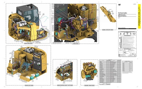
325F Excavator Electrical System
86
5
XAA10001-UP YCA10001-UP NDJ1-UP RBW1-UP
8
CONN 15 CONN 14 CONN 10
32
CONN 12
65
CONN 13
38 89 84
Volume 1 of 4: Chassis Wiring
53
BOOM - TOP LEFT VIEW
59 9
6
72
Harness And Wire Electrical Schematic Symbols Symbols
82 T
Pressure Symbol
71 CONN 7 CONN 8
Temperature Symbol
22
Fuse: A component in an electrical circuit that will open the circuit if too much current flows through it. Switch (Normally Open): A switch that will close at a specified point (temp, press, etc.). The circle indicates that the component has screw terminals and a wire can be disconnected from it. Switch (Normally Closed): A switch that will open at a specified point (temp, press, etc.). No circle indicates that the wire cannot be disconnected from the component.
50 45
44 40
47
19 12
CONN 2 CONN 1
48
RIGHT SIDE VIEW
43
80
Ground (Wired): This indicates that the component is connected to a grounded wire. The grounded wire is fastened to the machine. Ground (Case): This indicates that the component does not have a wire connected to ground. It is grounded by being fastened to the machine.
57
27
66
NOT NOT SHOWN SHOWN
14 24
26
7
36
37
55
73
13
Reed Switch: A switch whose contacts are controlled by a magnet. A magnet closes the contacts of a normally open reed switch; it opens the contacts of a normally closed reed switch.
1
35
Sender: A component that is used with a temperature or pressure gauge. The sender measures the temperature or pressure. Its resistance changes to give an indication to the gauge of the temperature or pressure.
CONN 6 T
REAR VIEW
33
Circuit Breaker Symbol
Flow Symbol
Symbols and Definitions
51 58
Level Symbol
Relay (Magnetic Switch): A relay is an electrical component that is activated by electricity. It has a coil that makes an electromagnet when current flows through it. The electromagnet can open or close the switch part of the relay. Solenoid: A solenoid is an electrical component that is activated by electricity. It has a coil that makes an electromagnet when current flows through it. The electromagnet can open or close a valve or move a piece of metal that can do work.
34
Magnetic Latch Solenoid: A magnetic latch solenoid is an electrical component that is activated by electricity and held latched by a permanent magnet. It has two coils (latch and unlatch) that make electromagnet when current flows through them. It also has an internal switch that places the latch coil circuit open at the time the coil latches.
Harness and Wire Symbols Wire, Cable, or Harness Assembly Identification: Includes Harness Identification Letters and Harness Connector Serialization Codes (see sample).
23 NOT SHOWN
Harness Identification Letter(s): (A, B, C, ..., AA, AB, AC, ...)
L-C12 3E-5179
AG-C4 111-7898
1
Part Number: for Connector Plug
92
L-C12 3E-5179
Harness Connector Serialization Code: The "C" stands for "Connector" and the number indicates which connector in the harness (C1, C2, C3, ...).
Part Number: for Connector Receptacle
2 Plug
20
Receptacle Pin or Socket Number
1 2
Deutsch connector: Typical representation of a Deutsch connector. The plug contains all sockets and the receptacle contains all pins.
1 2
Sure-Seal connector: Typical representation of a Sure-Seal connector. The plug and receptacle contain both pins and sockets.
5A 9X-1123
Fuse (5 Amps)
Component Part Number
325-AG135 PK-14
91
© 2017 Caterpillar All Rights Reserved
Harness identification code: This example indicates wire group 325, wire 135 in harness "AG".
CAT, CATERPILLAR, their respective logos, “Caterpillar Yellow”, and the POWER EDGE trade dress as well as corporate and product identity used herein, are trademarks of Caterpillar and may not be used without permission.
39 69 Component Location
62
Component
81
76 74
Schematic Location
Machine Location
Alarm - Travel
D-13
1
Sensor - Soot
Alternator
I-13
2
Sensor - Squeeze Atch
Batter - Front
I-5
3
CONN 4
31
CONN 5
68
10 17 18 67
16
2
4
30
64 63
29 79
78
3 15
88
77
75
61
83
21
90
NOT SHOWN
Sensor - Stick Out Control Pressure
B-6
51
Sensor - Tank Coolant Diverter Valve
I-7
52
CONN 1
J-16
6
Sensor - UREA Tank Header Unit
I-7
53
CONN 2
C-16
J-7
7
Sensor - Viscus Clutch Atch
I-13
54
CONN 3
I-11
H-16
8
Sensor - Water Separator Level
A-13
55
Ground - Chassis 2
I-3
9
Solenoid - A/C Clutch
H-13
56
CONN 4
B-7
Ground - Chassis A
E-11
10
Solenoid - Boom 2 Up Atch
C-10
57
CONN 5
B-7
Connector Number
Ground - Chassis B
A-9
11
Solenoid - Boom Down Atch
C-7
58
CONN 6
G-7
Ground - Chassis C
E-13
12
Solenoid - Boom Regen
D-4
59
Ground - Chassis D
I-13
13
Solenoid - Fine Swing Atch
G-7
60
CONN 7
E-6
Ground - Chassis F
H-14
14
Solenoid - Heavy Lift
C-4
61
CONN 8
D-6
Ground - Chassis G
F-10
15
Solenoid - Hyd Lock
D-4
62
CONN 9
G-3
Ground - Chassis H
A-9
16
Solenoid - NFC 1
E-6
63
CONN 10
F-3, F-1
Horn - Forward Warning LH
E-5
17
Solenoid - NFC 2
D-4
64
Horn - Forward Warning RH
E-5
18
Solenoid - Power Shift Pressure
A-13
65
CONN 11
D-3, C-3
Motor - Lifting Pump
B-16
19
Solenoid - QC Bypass Cut Atch
C-10
66
CONN 12
E-1
Motor - Refueling Pump Atch
A-10
20
Solenoid - Quick Coupler
A-6
67
CONN 13
F-1
Motor - Starter
J-13
21
Solenoid - Quick Coupler Hold To Run
A-6
68
CONN 14
G-1
Motor - Washer
H-4
22
Solenoid - Quick Coupler Unlock Atch
D-11
69
Potentiometer - Boom Atch
B-10
23
Solenoid - Smart Boom Down ELE Check Atch
C-7
70
CONN 15
J-1
Resistor - Can J1939 (DEF)
J-7
24
Solenoid - Smart Boom Up ELE Check Atch
C-7
71
A-15
25
Solenoid - Snubber
E-4
72
J-7
26
Solenoid - Start Aid
D-13
73
Sender - Fuel Level
A-13
27
Solenoid - Stem 1 Extend Sol X1 (Tool-20)
C-6
74
Sensor - Air Inlet Temperature
I-10
28
Solenoid - Stem 1 Retract Sol X1 (Tool-20)
C-6
75
Sensor - Boom Cylinder Head Pressure
F-6
29
Solenoid - Stem 2 Extend Sol X (Tool-20)
C-6
76
Sensor - Boom Cylinder Rod Pressure
F-6
30
Solenoid - Stem 2 Retract Sol X1 (Tool-20)
B-6
77
Sensor - Bucket Cylinder Head Pressure
B-6
31
Solenoid - Stem 3 Extend Atch (Medium Circuit)
F-7
78
Sensor - Charge Air Cool Out Temperature
G-16
32
Solenoid - Stem 3 Retract Atch (Medium Circuit)
F-7
79
Sensor - Def Fluid Injector
A-16
33
Solenoid - Stick In Atch
D-7
80
Sensor - DOC IN Temperature
A-16
34
Solenoid - Swing Brake
D-4
81
Sensor - DPF IN Temperature
82
A-16
35
Solenoid - Swing Priority
E-4
Sensor - Heater 1m
I-7
36
Solenoid - Travel Speed
C-4
83
Sensor - Heater 2m
I-7
37
Solenoid - Travel Straight
D-4
84
Sensor - Heater 3m
H-7
38
Solenoid - Variable Relief 1 Atch
C-1, D-1
85
Sensor - Hyd Oil Temperature
B-10
39
Solenoid - Variable Relief 2 Atch
C-1, D-1
86
Sensor - ID Module (DEF)
B-16
40
Switch - Air Cleaner Pressure
I-10
87
Sensor - NFC 1 Pilot Pressure
D-4
41
Switch - Bucket In Pressure
B-6
88
Sensor - NFC 2 Pilot Pressure
E-4
42
Switch - Dual Disconnect
I-4
89
Sensor - Pump 1 Pressure
D-4
43
Switch - Engine Oil Level
G-16
90
Sensor - Pump 2 Pressure
C-4
44
Switch - Hyd Oil Filter
B-10
91
Sensor - SCR IN Temperature
A-16
45
Switch - Refueling Atch
A-10
92
J-10
93
I-4
94
Sensor - SCR Inlet NOX
B-16
46
Switch - Shunt Tank
Sensor - SCR Outlet NEX
B-16
47
VLPM
Schematic Location A-6
Machine Location
Component Location
ENGINE - RIGHT SIDE
50
4
Camera - Side View (Atch)
MAIN CONTROL VALVE - LEFT SIDE
C-7
5
Component
FRONT LEFT VIEW
Sensor - Stick In Control Pressure Atch
Connector Location
I-5
Resistor - Can Soot 1 (DEF
11
48 49
J-4
Resistor - Can Soot 1
70
B-13 C-1, D-1
Box - Breaker
Glow Plug
41
Machine Location
Batter - Rear
Control - XNOX ACU
42
Schematic Location
Schematic Location C-16
Control - Engine ECM
60
Component
220
Wire Gauge Wire Color
The connectors shown in this chart are for harness to harness connectors. Connectors that join a harness to a component are generally located at or near the component. See the Component Location Chart.
(Dimensions: 56 inches x 35 inches)
28
42 Page,
UENR6237-01 VOL 1 of 4
87