Monitor Panel Engine Controller Engine/Pump Controller Attachment Controller
Component Identifiers (CID¹) For Engine/Pump Control (MID² No. 69) CID 91 96 110 167 168 190 286 291 374 376 581 586 587 590 598 600 1161 1162 1178
Component Throttle Position Signal Fuel Level Sensor Engine Coolant Temperature Sensor Alternator Voltage Of The Power Supply (keyswitch) Speed Sensor Signal For Engine Oil Pressure Decrease Fan Motor Proportional Reducing Valve Swing Brake Solenoid Valve Travel Alarm Proportional Reducing Valve For The Power Shift Pressure Engine Speed Dial Feedback Sensor For The Governor Actuator Engine Control Travel Speed Solenoid Hydraulic Oil Temperature Sensor Pump Delivery Pressure Sensor (Drive) Pump Delivery Pressure Sensor 2 (Idle) Boom Hold Pressure Sensor
¹ The CID is a diagnostic code that indicates which component is faulty. ² The MID is a diagnostic code that indicates which electronic control module diagnosed the fault.
Description
101
RD
Battery +
607
PK
Chassis Lamp
103
RD
Monitor
615
YL
Cab Lamp
105
RD
Key Switch
616
BU
Boom Lamp
109
RD
Alternator B+
638
WH
ATCH Beacon Relay
110
RD
Timer Relay B+
645
RD
Switch Panel to Boom Lamp Relay
112
PU
Main Power Relay Output
113
OR
Switch Panel/Radio
CID 1 2 3 4 5 6 42 91 94 100 110 164 168 172 175 247 253 254 261 262 263 268 273 274 320 342 617 1627
Component Injector Solenoid 1st Cylinder Injector Solenoid 2nd Cylinder Injector Solenoid 3rd Cylinder Injector Solenoid 4th Cylinder Injector Solenoid 5th Cylinder Injector Solenoid 6th Cylinder Injector Actuation Control Valve Backup Throttle Position Switch Fuel Pressure Sensor Engine Oil Pressure Sensor Engine Coolant Sensor Injector Pressure Sensor System Voltage Inlet Air Temperature Sensor Engine Oil Temperature Sensor J1939 Data Link Personality Module ECM Error Timing Sensor Calibration Analog Sensor Power Supply Voltage Digital Supply Sensor Check Programmable Parameters Turbocharger Compressor Outlet Press. Sens. Atmospheric Pressure Sensor Speed Timing Sensor Secondary Speed Timing Sensor Air Heater Relay Fuel Pump Relay
Component Identifiers (CID¹) For Valve Control (MID² No. 06A) CID 145 1522 1523 1593 1594 1595 1596 1597 1598 1609 1615 1657 1658 1665 1666
Component 12 V Power Supply Variable Relief #2 Check Solenoid Valve Variable Relief #1 Check Solenoid Valve ATT Valve #1 Extension ATT Valve #2 Extension ATT Valve #3 Extension ATT Valve #1 Retraction ATT Valve #1 Retraction ATT Valve #1 Retraction Squeeze Load Pressure Sensor 1 Way / 2Way Changeover Solenoid Valve Left Joystick Thumb Wheel Right Joystick Thumb Wheel Proportional Reducing Valve For Variable Relief Valve #2 Proportional Reducing Valve For Variable Relief Valve #1
Alarm Fault
F-2
G
Alarm Travel
A-4
3
Schematic Location
Machine Location
Sensor Negative Cont Pressure 1
A-12
E
Sensor Negative Cont Pressure 2
A-12
E
Component
Alternator
E-10
4
Sensor OLWD Pressure
B-3
E
Battery
E-12
5
Sensor Squeeze Pressure
B-5
E
Battery
E-11
5
Sensor Turbo Outlet Pressure
B-10
2
Breaker Alternator
H-9
1
Sensor WTR Separator Level
H-7
16
Clutch A/C
D-10
25
Solenoid 1Way/2Way Cont
B-5
17
646
RD
Switch Panel to Cab Lamp Relay
Control Engine / Pump
E-8
1
Solenoid Boom Down Line Out Off
C-9
20
A623
BU
Switch Panel to Chassis Lamp Relay
Control Wiper
F-2
G
Solenoid Fine Swing
C-3
18
Converter 12V 7A
F-3
13
Solenoid Flow Limit
A-12
19
Diode
I-11
1
Solenoid Hammer
A-9
H
Control Circuits
114
RD
Forward Horn
115
RD
Cab Lamp
763
BU
Travel Speed Solenoid
118
GY
Wiper/Washer
779
WH
Low Pressure ATCH Quick Coupler Solenoid
119
PK
Aux Ckt
780
PU
Quick Coupler SW to Solenoid
120
YL
12V 10A Converter 1
788
YL
Engine Speed -
123
WH
Aux Circuit
A701
GY
Injector #1
124
GN
A/C
A702
PU
Injector #2
I-8
1
Solenoid High Pressure Quick Cpl (A2)
B-2
24
Engine Control
Diode
F-12
4
Solenoid High Pressure Quick Cpl (A1)
C-2
17
Engine Speed Pickup
D-10
14
Solenoid Hyd Lock
C-8
20 D
Heater Unit
D-5
1
Solenoid Low Pressure Quick Cpl (A3)
B-2
Horn
C-1
6
Solenoid Power Shift Cont
A-10
E
Ind Unit
H-1
B
Solenoid Primary NFC
A-12
E
Injector 1 thru 6
C-10
2
Solenoid Pump 2 Flow Cont
A-12
E
I-3
C
Solenoid Pump Flow Cont
A-12
E
129
BU
Cigar Lighter
A703
BR
Injector #3
130
RD
Coolant Temp Sensor
A704
GN
Injector #4
Joystick
135
BU
Switched Conveter Output
A705
BU
Injector #5
Joystick
H-1
B
Solenoid Relief 1
B-5
E
139
OR
12V Mem Out
A706
GY
Injector #6
Lamp Boom
C-1
7
Solenoid Relief Boom 1
B-5
E
143
BR
Boom Float
A755
PK
Throttle Switch #1
Lamp Cab
G-1
8
Solenoid Relief Boom 2
B-5
E
147
PU
Atch Sol
A756
BU
Throttle Switch #2
Lamp Chassis
B-1
9
Solenoid Relief Check 1
A-5
17
149
RD
Boom Lamp
A757
GY
Throttle Switch #3
Lamp Dome
G-1
10
Solenoid Relief Check 2
B-5
24
Lighter
F-2
A
Solenoid Stem 1 Cont (A)
A-9
E
150
OR
Quick Coupler
A758
BR
Throttle Switch #4
151
GN
Neutral Start Limit Switch
A762
PU
Engine Speed +
152
BU
Lower Wiper/Washer
A768
BU
Backup EPR SW Valve to Power Switch Sol
154
RD
Neutral Start Limit Switch
A769
GY
Backup EPR SW Valve to Power Switch Sol
160
PU
Chassis Lamp
A770
PK
Electronic Pump Control Bypass Switch to Resistor
168
RD
Aux Circuit
F773
OR
Governor Acceleration
169
PK
Backup/Monitor Control
F774
WH
Governor Deceleration
175
RD
A/C Blower
H705
BR
Fuel Pump Relay
179
BU
12V 10A Converter 2
H792
BR
180
GN
Aux Circuit
M734
184
RD
E/P Control
M736
A-9
E
Solenoid Stem 2 Cont (A)
A-9
E
Motor Fuel Pump
H-7
25
Solenoid Stem 2 Cont (B)
A-9
E
H
Solenoid Stem 3 Cont (A)
B-9
E
Solenoid Stem 3 Cont (B)
B-9
E
Motor Washer
G-7
15
Solenoid Stem 4 Cont (A)
B-9
E
Pump Refueling
A-3
27
Solenoid Stem 4 Cont (B)
B-9
E
Relay Boom Float Disable
I-12
23
Solenoid Swing Brake
C-9
20
ATCH Boom Start Boom Up/Down Relay 1
Relay Beacon
G-8
1
Solenoid Travel Speed
C-9
20
BR
Travel Mode Switch
Relay Boom
I-8
23
Solenoid Travel Straight
C-9
20
BU
Governor Command
Relay Cab Lamp
I-8
23
Switch A/C Panel
D-1
G
Relay Chassis Lamp
I-8
23
Switch ACL
F-9
E
WH
Flow Limit Press Valve Solenoid
189
RD
Engine Governer Actuator
M738
OR
Prim NFC Press PRV
191
WH
Atch Fine Swing Cont SW
M739
YL
Solenoid Return 2
196
BU
INSP Lamp
M740
PK
Travel Straight Solenoid
M741
Solenoid Stem 1 Cont (B)
11
12
M737
Beacon Lamp
A
F-1
I-1
Fuel Pump
OR
F-2
D-10
WH
199
Meter Service Monitor
Motor Starter
188
Ground Circuits
Component Identifiers (CID¹) For Engine Control (MID² No.24)
Machine Location
Component
Description Lighting Circuits
Power Circuits
Schematic Location
GY
Travel Alarm Cancel
Motor Lower Wiper
Relay Fuel Pump
G-8
1
Switch Backup EPR Valve
G-2
B
Relay Heater
E-11
23
Switch Backup Governor
H-2
B
Relay Horn
I-8
23
Switch Boom Down
C-8
20
Relay Hydraulic Lock
H-8
23
Switch Boom Float Exchange
D-2
G
Relay Main
H-11
23
Switch Coolant Level
H-7
21
Relay Neutral Start
H-8
23
Switch Disconnect
G-9
23
Relay QC Safety Lever "ON" Coil
I-11
23
Switch Engine Oil Level
D-10
12
Relay QC Safety Lever Lock 1 Switch
I-11
23
Switch Fine Swing Control
D-2
D
M742
PU
AEC Model Switch
200
BK
Main Chassis
M743
GN
Travel Mode Switch
201
BK
Opr. Mon. Return
M744
PK
ATCH Boom Float Display Relay
210
BK
Converter Ground
M745
BU
ATCH Smart Boom Up/Down Relay 2
Relay QC Safety Lever Lock 2 Switch
I-11
23
Switch Hammer
A-9
E
211
BK
Converter Ground
M746
YL
ATCH Smart Boom Up/Down Relay 1
Relay QC Safety Lever Priority
I-10
23
Switch Hammer Foot
H-2
A
229
BK
Battery -
M747
PU
ATCH Boom Float Exchange
Relay Refueling Power
A-3
27
Switch Horn
I-3
C
235
BK
E/P Control Ground
M748
OR
ATCH Boom Down Pressure Sw
Relay Refueling Stop
C-3
27
Switch Hydraulic Filter
A-5
E
I-12
23
Switch Joystick Pressure
H-3
H
Basic Machine Circuits 304
WH
Start Relay Output
306
GN
Starter Relay Coil to Neut Start Switch
307
OR
308 310
M749
WH
ATCH Boom Check Solenoid 2
Relay Smart Boom Up/Down 1
R746
PK
Turbo Outlet Pressure
Relay Smart Boom Up/Down 2
I-11
23
Switch Key
G-1
B
Relay Start
H-11
23
Switch Neutral Start Limit
I-3
H
Relay Timer
I-9
23
Switch OLWD Alarm Cancel
D-3
G
Seat with Seat Heater
H-2
27
Switch One Touch Low Idle
H-1
B
Sender Hydraulic Temperature
A-4
A
Switch Panel
F-1
G
Sensor A/C Photo
F-1
G
Switch Quick Coupler
G-1
B
R747
GY
Atmospheric Pressure
Key Start To Neut Start Switch
892
BR
CAT Data Link -
YL
Main Power Relay Coil
893
GN
CAT Data Link +
PU
Start Aid Switch To Start Aid Solenoid
A893
OR
Fuel Pump
320
RD
Horn Relay To Horn Switch
F889
WH
Throttle
Sensor Atmospheric Pressure
B-11
2
Switch Refueling
A-4
26
321
BR
Backup Alarm Lamp Travel Alarm
G826
BR
Oil Pressure Sensor +5V
Sensor Coolant Temperature
B-11
2
Switch Refueling (NC)
A-3
26
322
GY
Forward Horn
G827
BU
Oil Pressure Sensor Return
Sensor Discharge Pressure 1
A-10
E
Switch Refueling (NO)
A-3
26
323
WH
ATCH Refueling Power Relay
G828
WH
Eng Pressure Sensor +5V
Sensor Discharge Pressure 2
A-10
E
Switch Refueling Start
A-3
26
325
PK
ATCH Refueling Stop Sw
G829
GN
Eng Pressure Sensor Return
Sensor Dual Cam SP/TMG (HIGH)
B-11
2
Switch Rotary
D-3
G
326
RD
Engine Shutdown Solenoid To Key Switch
G833
PK
Eng Temp Sensor Rtn
Sensor Dual Cam SP/TMG (LOW)
B-11
2
Switch Seat Heater
D-2
G
329
YL
ATCH Refueling Stop Relay
G849
BR
Inj Actuation Pressure
Sensor Engine Oil Pressure
C-11
2
Switch Str Pressure
I-2
C
Inlet Air Htr Relay
Sensor Engine Oil Temperature
B-11
2
Switch Throttle Position
H-1
B
Sensor FLY TMG Cal
B-11
2
Switch Travel Left
H-1
H
Sensor Fuel Level
A-4
26
Switch Travel Right
H-1
H
Sensor Fuel Pressure
C-11
2
Switch UP/Down
B-8
20
Sensor Inj Actuation Pressure
B-11
2
Switch Window Limit
G-1
G
Sensor Intake Air Temperature
B-11
2
365
YL
ATCH Refueling Start Relay Monitoring Circuits
403
GN
Alternator+C96 Term
G850
BU
G853
OR
Intake Air Temp
G854
PK
IAP Control Valve
405
GY
Opr. Mon. Oil Pressure (Low Setting)
G855
PU
IAPCV Common
410
WH
Opr. Mon. Fault Alarm
G856
WH
Timing Cal Probe +
412
BU
Opr. Mon. Coolant Level
G857
YL
Timing Cal Probe -
A = Inside of Cab Area
E = Inside of pump Compartment
430
BU
Opr. Mon. Air Filter
K843
GN
Stem 3 Extend Switch
B = Inside of Right Console Area
F = Inside of Engine Compartment
487
OR
Hyd. Oil Flow Switch
K844
GY
Stem 4 Extend Switch
C = Inside of Left Console Area
G = Around Dash Area
491
PK
Hyd. Oil Temp Sensor
K847
PU
Stem 3 Retract Switch
D = Swing Motor Area
H = Under Operators Platform
495
GN
Fuel Level Signal
K848
WH
Stem 4 Retract Switch
496
WH
Opr. Mon. Panel Hyd. Oil Level
K849
YL
Hammer Pressure Switch
C468
BU
Engine Oil Level
K850
BR
ATT Stem 2
E469
YL
Tool Pressure Sensor
K851
BU
Medium Line Pressure SW
E470
BR
Negative Cont. Pressure Sensor 1
K852
GN
Aux Hyd Pressure SW
E471
BU
Negative Cont. Pressure Sensor 2
K853
GY
Atch Pump 1 Control Valve
E472
GN
12V Supply From Valve Control
K854
OR
Atch Pump 2 Control Valve
E473
GY
Stem 1 Modulation
K855
PK
Seperator Valve
E474
OR
Stem 2 Modulation
K856
PU
Stem 1 Control Valve A
Schematic Location
Machine Location
CONN 1
C-12
2
CONN 2
G-12
23
Connector Number
PK
Stem 3 Modulation
K857
WH
Stem 2 Control Valve A
CONN 3
G-12
23
E476
PU
Stem 4 Modulation
K858
YL
Stem 3 Control Valve A
CONN 4
G-11
23
E480
WH
Overload Alm Cancel Sw
K859
BR
Stem 4 Control Valve A
CONN 5
G-10
23
F441
GN
Oil Temp
K860
BU
Stem 1 Control Valve B
CONN 6
G-10
23
H446
PK
O.L.W.D. Pressure Sensor
K861
GN
Stem 2 Control Valve B
CONN 7
I-10
23
CONN 8
G-7
H
H465
GN
Travel Alarm Cancel Indicator
K862
GY
Stem 3 Control Valve B
CONN 9
H-7
H
H466
BU
AEC Mode Indicator
K863
OR
Stem 4 Control Valve B
CONN 10
I-5
H
H467
WH
Travel Mode Indicator 1
K864
PK
ATT Relief Valve Solenoid 1
CONN 11
E-6
13
H473
BR
Travel Straight Pressure Switch
K865
PU
ATT Relief Valve Solenoid 2
CONN 12
A-6
H
CONN 13
E-6
E
GN
Travel Right Pressure Switch
K866
WH
ATT 1-Way/2-Way Control Valve Solenoid
H475
BU
Travel Left Pressure Switch
K867
YL
ATT Solenoid Return 1
H476
WH
Joystick Pressure Switch Accessory Circuits
CONN 14
F-5
E
CONN 15
F-4
H
K868
BR
ATT Solenoid Return 2
CONN 16
E-4
G
K869
BU
ATT Solenoid Return 3
CONN 17
E-4
G
501
GN
Wiper - Front (Low)
K870
GN
ATT Solenoid Return 4
CONN 18
E-4
G
506
PU
Washer - Front
K876
BR
ATT Relief Check Valve Solenoid 1
CONN 19
D-4
G
508
PU
Radio Speaker - Left
K877
BU
ATT Relief Check Valve Solenoid 2
CONN 20
B-4
26
CONN 21
B-4
26
CONN 22
G-3
H
CONN 23
H-3
H
509
WH
Radio Speaker - Left (Common)
954
GN
ATCH Hammer Solenoid
511
BR
Radio Speaker - Right
995
BU
Coolant Temp
512
GN
Radio Speaker - Right (Common)
998
BR
Throttle Return
CONN 24
H-3
H
530
OR
Washer
C987
RD
Atch Valve Cont +B
CONN 25
H-3
H
578
BU
Washer - Aux.
C990
YL
Eng Oil Pressure
CONN 26
I-3
C
586
BR
Not Used
C991
PK
Fuel Pressure
CONN 27
I-3
C
590
GY
Wiper Switch To Intermittent Module
E963
BK
Top Cam S/T -
CONN 28
C-2
H
A537
PK
Not Used
E964
WH
Top Cam S/T +
CONN 29
C-2
28
CONN 30
F-1
G
A579
OR
Wiper Motor +
E965
BU
Bottom Cam S/T -
A580
GN
Wiper Motor -
E966
YL
Bottom Cam S/T+
A584
BU
Front Window Limit Switch to Wiper Cont.
G976
BU
Water Separator Sensor
A586
OR
Wiper Switch. To Wiper Cont
K904
GN
Pump Discharge Pressure Sensor 1 - Signal
A588
GN
Hyd Lock Sol. Relay to Hyd Lock Sol.
K906
GN
Swing Brake Sol - Signal
C537
GN
A/C Photo Sensor + Sig
K907
BU
Swing Brake Cancel Sol
C538
OR
A/C Photo Sensor - Sig
L968
OR
E/P Control PS Valve -
C569
YL
Second DC/DC Converter Power Output
L969
WH
E/P Control PS Valve +
E554
PK
A/C Controller to A/C Compressor Clutch
L972
BU
Low Idle Switch
E562
PU
Buzzer As
L973
GN
Fine Swing Control Relay to Sol Valve
E564
PK
Relay
L976
GN
ATCH Refueling Start Sw (NO)
E565
BU
Rotary Sw
L983
WH
Injector Common 1&2
L984
OR
Injector Common 3&4
L985
YL
Injector Common 5&6
M906
BU
Squeeze Pressure Sensor
T967
YL
Pump Discharge Pressure Sensor 2 - Signal
Symbols
T
Pressure Symbol
Temperature Symbol
Level Symbol
Flow Symbol
Circuit Breaker Symbol
Symbols and Definitions Fuse: A component in an electrical circuit that will open the circuit if too much current flows through it. Switch (Normally Open): A switch that will close at a specified point (temp, press, etc.). The circle indicates that the component has screw terminals and a wire can be disconnected from it. Switch (Normally Closed): A switch that will open at a specified point (temp, press, etc.). No circle indicates that the wire cannot be disconnected from the component. Ground (Wired): This indicates that the component is connected to a grounded wire. The grounded wire is fastened to the machine. Ground (Case): This indicates that the component does not have a wire connected to ground. It is grounded by being fastened to the machine. Reed Switch: A switch whose contacts are controlled by a magnet. A magnet closes the contacts of a normally open reed switch; it opens the contacts of a normally closed reed switch.
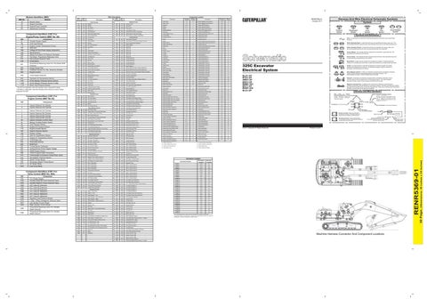
325C Excavator Electrical System
Sender: A component that is used with a temperature or pressure gauge. The sender measures the temperature or pressure. Its resistance changes to give an indication to the gauge of the temperature or pressure.
T
Relay (Magnetic Switch): A relay is an electrical component that is activated by electricity. It has a coil that makes an electromagnet when current flows through it. The electromagnet can open or close the switch part of the relay.
BLA1-UP BTD1-UP AMH1-UP BKH1-UP BMM1-353 BKT1-UP BKW1-236 BLX1-UP
Solenoid: A solenoid is an electrical component that is activated by electricity. It has a coil that makes an electromagnet when current flows through it. The electromagnet can open or close a valve or move a piece of metal that can do work. Magnetic Latch Solenoid: A magnetic latch solenoid is an electrical component that is activated by electricity and held latched by a permanent magnet. It has two coils (latch and unlatch) that make electromagnet when current flows through them. It also has an internal switch that places the latch coil circuit open at the time the coil latches.
Harness and Wire Symbols Wire, Cable, or Harness Assembly Identification: Includes Harness Identification Letters and Harness Connector Serialization Codes (see sample).
Harness Identification Letter(s): (A, B, C, ..., AA, AB, AC, ...)
L-C12 3E-5179
AG-C4 111-7898
L-C12 3E-5179
1
Part Number: for Connector Plug
Harness Connector Serialization Code: The "C" stands for "Connector" and the number indicates which connector in the harness (C1, C2, C3, ...).
Part Number: for Connector Receptacle
2 Plug
Receptacle Pin or Socket Number
1 2
Deutsch connector: Typical representation of a Deutsch connector. The plug contains all sockets and the receptacle contains all pins.
1 2
Sure-Seal connector: Typical representation of a Sure-Seal connector. The plug and receptacle contain both pins and sockets.
5A Fuse (5 Amps)
9X-1123
Component Part Number
325-AG135 PK-14
© 2011 Caterpillar All Rights Reserved
Harness identification code: This example indicates wire group 325, wire 135 in harness "AG".
Wire Gauge Wire Color
Printed in U.S.A.
Connector Location
E475
H474
Harness And Wire Electrical Schematic Symbols
RENR5369-01 October 2011
CONN 31 H-3 H The connectors shown in this chart are for harness to harness connectors. Connectors that join a harness to a component are generally located at or near the Component. See the Component Location Chart.
23
C
16
15
A
5
10
8
11
13
21
H
B
1 G
7
24
25
28
D 2
6
18 4
22
12
F
20 26
14
17
E 27
9
3 19
8 10
7
A
23
E
25
16
2
14
4
12
1 26
21 15
24
5
28
C
G
B 11
18 6
D
22 19
17
13
F
3
20
27
9
H
Machine Harness Connector And Component Locations
(Dimensions: 39 inches x 28 inches)
Module
Wire Wire Number Color
30 Page,
MID No. 1E 24 69 6A
Component Location
Wire Description Wire Wire Number Color
RENR5369-01
Module Identifiers (MID)