RENR9649-02 September 2009
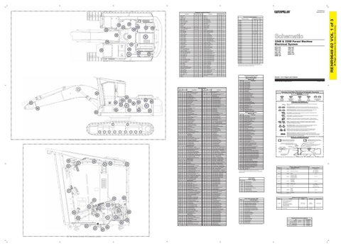
Component Location for Volume 1
A-15
30
Alternator
G-16
B
F-7 H-10
Assembly - Block Battery - Front
30
35
29
31
33
28
38
44
B
34 44
32
27
A
A
C-5
A
A
Relay - Horn
K-6
A
A
Relay - Main
G-7
A
H-10
A
Relay - Neutral Start
J-6
A
H-10
A
Relay - Priming Pump
K-5
25
Battery - (Rear) (ATCH)
H-10
A
Relay - Rear Work Light
H-5
A
Breaker - Alternator
G-6
A
Relay - Riser Lamp
I-5
A
Breaker - Heater
G-6
A
Relay - Start
G-7
A
Connector Location Volume 1 Schematic Location
Connector Number
I-18
25
CONN 2
J-17
25
CONN 3
J-17
25
CONN 4
J-17
25
D-17
B 25
Breaker - Main
G-6
A
Relay - Travel Alarm
J-6
A
Buss Bar
G-6
A
Resistor - Backup
K-7
A
CONN 6
L-15
Control - Engine
E-18 to H-18
B
Resistor - Can #1
A-6
A
CONN 7
K-13
27
J-16
25
Resistor - Can #2
A-6
A
CONN 8
I-13
27
B-6 to D-6
25
Resistor #2
J-8
A
CONN 9
I-13
17
K-5
A
Sender - Fuel CWCT (ATCH)
B-18
B
CONN 10
B-13
35
Control - Gateway Worldview ECM Control - Machine ECM Diode - Main Relay
G-7
A
Sender - Hydraulic Temperature
A-15
29
CONN 11
A-13 ; B-13
A
Diode - Start Relay
G-7
A
Sensor - Engine Speed Pickup
F-17
B
CONN 12
A-13 ; B-13
40
Ground - CTWT
K-18
25
Sensor - Fuel Level
C-12
31
CONN 13
A-12 ; B-12
39
Ground - ECM Mount
I-16
25
Sensor - Fuel Pressure
L-13
27
CONN 16
A-10
26 26
Ground - Frame 1
G-11
32
Sensor - Fuel Temperature
L-13
27
CONN 17
B-10
Ground - Frame 2
F-14
32
Sensor - Pump #1 Pressure
C-18
33
CONN 18
B-10
26
Ground - Frame 3
F-17
B
Sensor - Pump #2 Pressure
C-18
33
CONN 19
C-10
26
Ground - Frame 4
B-14
26
Sensor - Squeeze Pressure (ATCH)
C-10
26
Ground - Frame 5
F-8
A
Sensor - Water Separator Level
K-13
27
CONN 20
E-10
29
Ground - Frame 6-1
J-13
32
Sensor - Water Separator Level-2
B-18
27
CONN 21
E-10
29
Ground - Frame 6-2
H-10
32
Solenoid - 1Way/2Way Change (ATCH)
C-10
35
CONN 22
F-10
29
F-1
42
Solenoid - A/C Clutch
G-16
B
CONN 24
E-8
25
CONN 25
J-7
25
Ground - Panel
G-7
A
Solenoid - Ether (ATCH)
L-13
Ground Point - Block
H-10
B
Solenoid - Fuel Select (ATCH)
B-18
27 B
CONN 26
I-7
25
Ground - Riser-1
F-1
42
Solenoid - Fine Swing
C-10
26
CONN 27
H-7
A
Head - Harvester
A-11
39
Solenoid - Flex Fan (ATCH)
D-18
28
CONN 28
F-6
A
Heater - Air
G-17
B
Solenoid - Flow Limit (ATCH)
C-18
28
CONN 29
F-6
A
A-9
26
Solenoid - Heavy Lift
F-10
34
CONN 30
H-5
A
Horn - Forward Warning (RH)
A-9
26
Solenoid - Hydraulic Lock
G-10
34
CONN 31
F-5
A
Indicator - Air Cleaner
J-13
32
Solenoid - Power Shift Pressure
C-18
33
CONN 32
F-5
A
Lamp - Boom Lamp (LH) (ATCH)
B-9
43
Solenoid - Relief #1 (ATCH)
D-10
26
CONN 33
F-4
A
Lamp - Boom Lamp (RH) (ATCH)
B-9
43
Solenoid - Relief #1 (Check) (ATCH)
D-10
26
CONN 34
F-4
A
Lamp - Cab Lamp (LH)
I-6
42
Solenoid - Relief #2 (ATCH)
C-10
35
CONN 35
L-3
17
Lamp - Chassis (LH)
B-12
26
Solenoid - Relief #2 (Check) (ATCH)
C-10
35
CONN 36
K-3 ; L-3
17
Lamp - Chassis (RH)
B-12
26
Solenoid - Stem #1 Extend (ATCH)
B-16
28
CONN 37
J-3
17
Lamp - Riser (LH)
H-1
26
Solenoid - Stem #2 Extend (ATCH)
A-18
28
CONN 38
F-3
A
Lamp - Riser (RH)
H-1
26
Solenoid - Stem #3 Extend (ATCH)
B-18
28
CONN 39
F-3
A
Lamp - Stick Lamp (LH) (ATCH)
B-9
44
Solenoid - Stem #1 Retract (ATCH)
B-16
28
Lamp - Stick Lamp (RH) (ATCH)
B-9
44
Solenoid - Stem #2 Retract (ATCH)
A-18
28
CONN 40
F-2
A
Motor - A/C Condenser Fan
J-13
41
Solenoid - Stem #3 Retract (ATCH)
B-18
28
CONN 41
H-2
17
Motor - Lower Washer
H-2
41
Solenoid - Swing Brake
G-10
34
CONN 42
K-1 ; L-1
24
Motor - Starter
F-17
B
Solenoid - Travel Speed
G-10
34
CONN 43
I-1 ; J-1
24
Motor - Washer
I-2
41
Solenoid - Travel Straight
G-10
34
Pump - Priming
J-13
27
Switch - Coolant Level
L-13
27
Pump - Priming (ATCH)
I-13
27
Switch - Disconnect
F-8
A
Radio - Product Link 2nd Generation
K-18
25
Switch - Engine Oil Level
F-17
B
Receptacle - Jump Start (ATCH)
H-10
32
Switch - Fuel Pressure
L-13
27
Relay - Air Heater
G-17
B
Switch - Hammer Return Filter (ATCH)
E-12
38
Relay - Boom Lamp
K-6
A
Switch - Hydraulic Oil Filter
A-15
29
Relay - Cab Lamp
K-6
A
Switch - Hydraulic Oil Level
A-15
31
Relay - Cab Lamp LH
I-6
A
Switch - Priming Pump
J-13
27
Relay - Chassis Lamp
K-6
A
Switch - Priming Pump (ATCH)
I-13
27
Relay - Ether
J-6
A
Switch - Secondary Shutdown
K-13
32
Relay - 1
D-5
A
Unit - Power
J-13
32
Relay - 2
D-5
A
Wire Description Wire Number
Wire Color
101
RD
Description
Wire Number
Wire Color
L620
GN
Power Circuits
25 34 26
43
38
31 39
33
41
32
A
35
28
B 30
42
Machine Harness Connector And Component Locations
29
27
Bat (+) (Not Application Specific)
Component Identifiers (CID¹) Module Identifier (MID²) Engine Control System (MID No. 036)
10
3
14
5
16
8
13
21 9
6
11 2
36
12 1
19
4 15 23
37 17
Cab View Harness Connector And Component Locations
20 24
Injector Cylinder #2
0003
Injector Cylinder #3
0004
Injector Cylinder #4
0005
Injector Cylinder #5
0006
Injector Cylinder #6
0041
8 Volt DC Supply
0042
Injector Actuation Valve
0091
Throttle Position
0094
Fuel Pressure
0100
Engine Oil Pressure
Dome Lamp, Service Meter
L625
YL
Cab Lamp LH Relay to Cab Lamp LH
0110
Engine Coolant Temperature
Key Switch
L831
GY
Rear Flood Lamp (ATCH)
0164
Injector Actuation Pressure
0168
Electrical System Voltage
Control Circuits
108
BU
Heater Breaker
109
RD
Alt Output (+) Term.
763
BU
Torque Converter SW
0172
Intake Manifold Air Temperature
112
PU
Main Power Relay Output
788
YL
Engine Speed Pickup Sensor (+)
0174
Fuel Temperature
113
OR
Switch Panel (B+)
A751
YL
After Cooler Temp (Pin 15)
0190
Engine Speed Sensor
114
GN
Warning Horn (Forward) Relay
A755
PK
Throttle Position Switch #1
0253
Personality Module
PK
Cab Lamp Relay
A756
BU
Throttle Position Switch #2
0261
Engine Timing Calibration
GY
Wiper Control
A757
GY
Throttle Position Switch #3
0262
5 Volt DC Sensor Power Supply
119
PK
Work Light
A758
BR
Throttle Position Switch #4
0268
Check Programmable Parameters
120
YL
12V 10A Converter 1
A762
PU
Electronic Pump Cont Eng Speed Gnd
0274
Atmospheric Pressure
124
GN
A/C Unit
A768
BU
Pump Control Valve #1 (+)
0286
EMS Oil Lamp
125
RD
A/C Unit
A769
GY
Pump Control Valve #2 (-)
0342
Secondary Engine Speed
127
OR
Air Suspension (ATCH)
A770
PK
Electronic Pump Ctl Bypass SW to Resistor
0617
Air Inlet Heater Machine Security System
129
BU
Cigar Lighter
F716
WH
Shutdown (NC)
1639
GN
Engine Control
F773
OR
Governor Accel
1785
Intake Manifold Pressure Sensor
135
BU
12V 10A Converter 1
F774
WH
Governor Decel
2417
Ether Injection Control Solenoid
139
OR
Radio (ATCH)
G723
YL
Heavy Lift Solenoid
141
PK
Priming Pump Relay
H704
PK
Impl Cont Reversing Fan Solenoid
BU
Priming Pump Relay (ATCH)
H746
YL
Fan Control Solenoid (+)
Aux Ckt
H747
BR
Fan Control Solenoid (-)
147
PU
Water Separator Level Sensor
J716
OR
CTWT Fuel Relay (ATCH)
149
RD
Boom Lamp Relay
J717
BU
CTWT Fuel Level Sensor
152
BU
Wiper Control
K791
OR
Reversing Fan SW (Manual)
154
WH
Neutral Start Relay Coil
K792
GN
Relay 2 to Relay 4
160
PU
Chassis Lamp Relay
K796
WH
Cut Thru 30 Thread (Harvester Control Box)
166
YL
Cab Fan (ATCH)
K797
OR
Color 1 (Harvester Control Box)
167
OR
Switch (ATCH)
K798
PU
Color 2 (Harvester Control Box)
169
PK
Backup EPR Valve Switch
K799
GN
Clamp Arm High Pressure (Harvester Box)
172
GN
Gateway Worldview Module
M736
BU
Governor Command
177
OR
Main Breaker
M737
WH
Front Flow Control Valve Solenoid
179
BU
12V 10A Converter 2
M739
YL
Solenoid Return 2
180
GN
Aux Ckt 1
M740
PK
Travel Straight Solenoid
184
BU
Machine (ECM)
M743
GN
Boom Float Disable Relay
189
WH
Neutral Start Limit Switch
N707
PU
Engine Digital Sensor Return
191
WH
Lamp Controls, Fine Swing Control
N743
WH
Relay 3 to Relay 2
198
PK
Rear Work Light Relay
R725
WH
Fuel Filter Sw
199
OR
Fault Alarm
T725
WH
Fuel Filter Sw
Ground Circuits
T788
GN
Priming Pump Relay
200
BK
Main Chassis
X738
PK
Return Filter SW to Controller
210
BK
12V 10A Converter 1
892
BR
CAT Data Link (-)
229
BK
12V 10A Converter 2, Engine Control
893
GN
CAT Data Link (+)
235
BK
Electronic Pump Control Gnd
A893
OR
Fuel SW to Fuel Pump
251
BK
Payload Mon System Gnd
C873
BU
Priming Pump SW (ATCH)
252
BK
VMIS Main Module Harness Code 0
C875
PU
Priming Pump Relay (ATCH)
261
BK
TEHC Ident Code 1
F889
WH
Throttle Position Feedback
262
BK
TEHC Ident Code 2
G828
WH
Fuel Pressure Sensor
A209
BK
Hex Machine Ctrl Gnd
G829
GN
Fuel Pressure Sensor
G833
PK
Fuel Temperature Sensor
304
WH
Starter Relay No. 1 Output
H837
BU
Roller Motor (+24V) (Harvester Control)
306
GN
Starter Relay Coil To Neutral Start Switch
H838
YL
Pulse Length Sender (GND) (Harvester Ctl)
307
OR
Neutral Start Switch To Key Switch
H839
WH
Roller Arm Close (Harvester Control)
308
YL
Main Power Relay Coil
H840
BR
Saw Sensor Signal (+) (Harvester Ctl)
310
PU
Start Aid SW To Start Aid Solenoid
H841
GN
Pulse Length Sender (P 1) (Harvester Ctl)
317
YL
Start Aid Relay To Start Aid Solenoid
H842
BU
Pulse Length Sender (P 2) (Harvester Ctl)
320
OR
Horn Relay Coil To Horn Switch
H843
YL
Saw Crosscut (Harvester Control)
321
BR
Travel Alarm Relay To Travel Alarm Lamp
H844
BR
Roller Arm Open (Harvester Control)
322
GY
Warning Horn (Forward) To Horn Relay
H845
WH
Tilt Up
326
PU
Key Switch 'C' Terminal
H846
PK
Tilt Down (Harvester Control)
(Harvester Control)
331
OR
Travel Alarm Relay To Switch Panel
H847
GN
Clamp Arm In (Harvester Control)
Monitoring Circuits
H848
WH
Clamp Arm Out (Harvester Control)
251
BK
Can #1 Resistor
H849
OR
Knives Close
(Harvester Control)
252
BK
Can #2 Resistor
H850
BR
Knives Open
(Harvester Control)
261
GN
Can #1 (-)
H851
PU
Roller Arm High Pressure (Harvester Ctl)
262
GN
Can #2 (-)
H852
GN
Saw Bar In (Harvester Control)
403
GN
Alternator (R) Terminal
H853
YL
Rollers Motor
405
GY
Opr Mon Oil Pressure (Low Setting)
H854
BU
Knives High Press (Harvester Control)
(Harvester Control)
410
WH
Opr Mon Fault Alarm
H855
OR
Cut Thru 25 Thread (Harvester Control)
412
BU
Opr Mon Coolant Level Switch
H856
BR
Sensor (+24V) (Harvester Control)
430
BU
Opr Mon Air Filter Switch
H857
PK
UREA
487
OR
Hydraulic Oil Flow Switch
H858
WH
Pulse Diameter Sender P 1 (Harvest Ctl)
(Harvester Control)
491
PK
VMIS Hydraulic Oil Temperature Sender
H859
GN
Pulse Diameter Sender P 2 (Harvest Ctl)
495
GN
VMIS Fuel Level Sensor
H860
YL
Pulse Dia Sender Grd Return (Harvester Ctl)
496
WH
Opr Mon Panel Hydraulic Oil Level
K843
GN
Stem 3 Extend SW (Joystick (RH))
C468
BU
Opr Mon Engine Oil Level
K844
GY
Stem 4 Extend SW (Joystick (LH))
CID 8 Volt DC Supply
0096
Fuel Level Sensor
0110
Engine Coolant Temperature Sensor
0167
Alternator Charging Voltage Sensor
0168
Electrical System Voltage
0171
Ambient Air Temperature Sensor
0190
Engine Speed Sensor
0246
Proprietary CAN Data Link
0247
SAE J1939 Data Link
0248
CAT Data Link
Fuse: A component in an electrical circuit that will open the circuit if too much current flows through it.
Switch (Normally Closed): A switch that will open at a specified point (temp, press, etc.). No circle indicates that the wire cannot be disconnected from the component. Ground (Wired): This indicates that the component is connected to a grounded wire. The grounded wire is fastened to the machine.
Reed Switch: A switch whose contacts are controlled by a magnet. A magnet closes the contacts of a normally open reed switch; it opens the contacts of a normally closed reed switch. Sender: A component that is used with a temperature or pressure gauge. The sender measures the temperature or pressure. Its resistance changes to give an indication to the gauge of the temperature or pressure. Relay (Magnetic Switch): A relay is an electrical component that is activated by electricity. It has a coil that makes an electromagnet when current flows through it. The electromagnet can open or close the switch part of the relay.
0254
Electronic Control Module
0262
5 Volt DC Sensor Power Supply
0271
Action Alarm
0291
Engine Cooling Fan Solenoid
0362
Engine Speed Fan Control Solenoid
0374
Swing Brake Solenoid
0485
Engine Fan Reversing Solenoid
0544
Engine Cooling Fan Speed Sensor
0581
Power Shift Solenoid
0586
Engine Speed Dial Switch
0588
Monitoring System Display
0590
Engine Control Module
Solenoid: A solenoid is an electrical component that is activated by electricity. It has a coil that makes an electromagnet when current flows through it. The electromagnet can open or close a valve or move a piece of metal that can do work. Magnetic Latch Solenoid: A magnetic latch solenoid is an electrical component that is activated by electricity and held latched by a permanent magnet. It has two coils (latch and unlatch) that make electromagnet when current flows through them. It also has an internal switch that places the latch coil circuit open at the time the coil latches.
Harness and Wire Symbols
0598
Travel Speed Solenoid
0600
Hydraulic Oil Temperature Sensor
0735
Heavy Lift Solenoid
1129
Right Attachment Pedal Position Sensor
1130
Left Attachment Pedal Position Sensor
1160
Hydraulic Lock Solenoid
1178
Machine Overload Warning Pressure Sensor
1522
Relief Valve #2 Check Valve Solenoid
1523
Relief Valve #1 Check Valve Solenoid
1525
Straight Travel Solenoid
1590
Main Pump Flow Limitation Pressure Solenoid
Deutsch connector: Typical representation of a Deutsch connector. The plug contains all sockets and the receptacle contains all pins.
1 2
1594
Attachment Valve #2 Extend Pressure Solenoid
1595
Attachment Valve #3 Extend Pressure Solenoid
1596
Attachment Valve #1 Retract Pressure Solenoid
1597
Attachment Valve #2 Retract Pressure Solenoid
1598
Attachment Valve #3 Retract Pressure Solenoid
1609
F2 Type Valve Load Sense Pressure Sensor
1657
Left Joystick Thumbwheel
1658
Right Joystick Thumbwheel
1665
Variable Relief Valve #1 Pressure Solenoid
1666
Variable Relief Valve #2 Pressure Solenoid
1931
Auxiliary Circuit Flow Combining Solenoid
2265
Hydraulic Pump #1 Outlet Pressure Sensor
2266
Hydraulic Pump #2 Outlet Pressure Sensor
2275
Hammer Return to Tank Solenoid
2280
Travel Alarm Relay
2300
Switch Panel
C-C4 130-6795
² The MID is a diagnostic code that indicates which electronic control module diagnosed the fault.
K847
PU
Stem 3 Retract SW (Joystick (RH))
WH
Stem 4 Retract SW (Joystick (LH))
E474
OR
Stem 2 Modulation Joystick (LH)
K849
YL
Hammer Pressure Switch (ATCH)
H475
BU
Travel Left Pressure Switch
K856
PU
Stem #1 Extend Solenoid
H476
WH
Joystick Pressure Switch
K857
WH
Stem #2 Extend Solenoid
K858
YL
Stem #3 Extend Solenoid
Event Code
K860
BU
Stem #1 Retract Solenoid
E096
High Fuel Pressure
Socket
Condition
PU
Washer - Front
K861
GN
Stem #2 Retract Solenoid
E162
High Boost Pressure
PU
Radio Speaker - Left
K862
GY
Stem #3 Retract Solenoid
E198
Low Fuel Pressure
509
WH
Radio Speaker - Left (Common)
K864
PK
Relief #1 Solenoid
E265
User Defined Shutdown
511
BR
Radio Speaker - Right
K865
PU
Relief #2 Solenoid
512
GN
Radio Speaker - Right (Common)
K866
WH
Att 1-Way / 2-Way control Valve
E360
Low Engine Oil Pressure
514
PU
A/C Unit to A/C Condenser Fan Motor
K868
BR
Att Solenoid Return 2
E361
High Engine coolant Temperature
530
OR
Washer Control
K869
BU
Att Solenoid Return 3
E362
Engine Overspeed
535
BU
Lower Wiper Control To Motor
K871
WH
1P/2P Pump Exchange Solenoid #1 & #2
E390
Fuel Filter Restriction
Pin or Socket Number
Ground Connection
4I-5394
Sender:
Wire Gauge
Resistance (Ohms)¹ 24.9 ± 0.4
102-8016
Resistor:
Backup
Solenoid:
ATCH Stem 1 Extend ATCH Stem 1 Retract ATCH Stem 2 Extend ATCH Stem 2 Retract
E539
High Intake Manifold Air Temperature
121-1491
Solenoid:
171-0188
Soleniod
163-6700
Sender:
174-3016
Resistor:
Solenoid:
ATCH Ether
Att Relief Solenoid
239-1134
586
BR
Aux Hyd - Close Fuel Switch Relay
K877
BU
ATT Change Check Solenoid
¹ At room temperature unless otherwise noted.
998
BR
Wiper Motor (-) To Wiper Control
C903
BU
Harvester Control to Relay 1
A586
OR
Wiper Switch To Wiper Control
C904
GN
Relay to Relay
A588
GN
Neutral Start Limit Switch
C905
OR
Harvester Control to Relay 4
C506
WH
A/C Condenser Fan Motor Hi Relay
C991
PK
Fuel Pressure Sensor
0
Data valid but above normal operational range.
Half = 33.8 ± 2.0
CAN #1 CAN #2 Resistor Resistor 2
Single Action Solenoid #1 & #2
Wiper Motor (+) To Wiper Control
11.5 ± 0.5 Empty = 83.5 ± 1.5
Full = 8.0 (+ 1.0) (-0.5)
BR
BR
32.0 ± 3.2
Fuel Level
OR
OR
11.7 ± 1.2
ATCH Flow Limit
K876
A579
47 ± 2.4
Hydraulic Lock Swing Brake Travel Speed Travel Straight
K872
A580
20K - 25K @ 0° C 9.7K - 1.2K @ 75° C 220 - 270 @ 125° C
Hydraulic Oil Temperature
Lower Wiper Sw To Lower Wiper Motor AUX
Digital Sensor Return
Wire Color
ATCH Flex Fan
Lower Washer Sw To Lower Wiper AUX
Switch Panel Option SW
Circuit Identification Number
Component Description Solenoid:
PK
Switch Panel Option SW
200-L32 BK-14
Resistor, Sender and Solenoid Specifications
BU
BU
Fuse (5 Amps)
Component Part Number
2
Harness identification code: This example indicates wire 135 in harness "AG".
576
BR
9X-1123
Plug
578
L885
5A
Receptacle
Event Codes Engine Control
506
L886
Part Number For Connector Recepticle
1
Single Wire Connector
111-9916
508
Wiper - Intermittent Module
L-C12 3E-5179
AG-C4 111-7898
¹ The CID is a diagnostic code that indicates which circuit is faulty.
K848
Seat Heater
Harness Connector Serialization Code: The "C" stands for "Connector" and the number indicates which connector in the harness. (C1, C2, C3, .....)
325-AG135 PK-14
3E-9205
Stem 1 Modulation Joystick (RH)
PK
Harness Identification Letter(s): (A, B, C, ..., AA, AB, AC, ...)
Part Number for Connector Plug
AG-C3 130-6795
Part No.
ATT 12v Sensor Supply (Machine ECM)
GY
Sure-Seal connector: Typical representation of a Sure-Seal connector. The plug and receptacle contain both pins and sockets.
1 2
Wire, Cable, or Harness Assembly Identification: Includes Harness Identification Letters and Harness Connector Serialization Codes
Pin
Attachment Valve #1 Extend Pressure Solenoid
GY
590
Circuit Breaker Symbol
Flow Symbol
Symbols and Definitions
T
GN
A537
Level Symbol
Ground (Case): This indicates that the component does not have a wire connected to ground. It is grounded by being fastened to the machine.
E473
Wiper Control - Front (Low)
Temperature Symbol
Component
0041
1593
Printed in U.S.A.
Symbols
Machine Control System (MID No. 039)
E472
GN
© 2009 Caterpillar, All Rights Reserved
Switch (Normally Open): A switch that will close at a specified point (temp, press, etc.). The circle indicates that the component has screw terminals and a wire can be disconnected from it.
130
BU
Volume 1 of 3: Engine and Chassis
T
115
142
JGK1-UP JKR1-UP JLS1-UP DAT1-UP BZW1-UP
Pressure Symbol
118
145
DFC1-UP BBF1-UP C7K1-UP C8L1-UP C9M1-UP DNR1-UP
Harness And Wire Electrical Schematic Symbols
YL
120 ± 12
20
Off Machine Switch Specification Failure Mode Identifiers (FMI)¹ FMI No.
Part No.
Function
167-3466
ATCH Aux Hydraulic Pressure ATCH Hammer Pressure Joystick Pressure ATCH Medium Line Pressure ATCH Travel Straight Pressure Travel Left Pressure Travel Right Pressure
212-2768
Fuel Pressure
Failure Description
C509
WH
A/C Thermostat
E997
BR
Hydraulic Lock Diode
1
Data valid but below normal operational range.
C560
OR
Left Rear Speaker
G973
OR
Boom Raise Pressure Switch
2
Data erratic, intermittent, or incorrect.
C566
PK
Left Rear Speaker (Common)
G976
BU
Water Separator Level Sensor
3
Voltage above normal or shorted high.
C569
YL
12V 10A Converter 2 Output
K904
GN
Pump #1 Pressure Sensor
4
Voltage below normal or shorted low.
C575
PK
Grapple Auto/Man SW Jumper
K906
GN
Swing Brake Solenoid - Signal
5
Current below normal or open circuit.
C584
WH
Speed Control Signal
K907
BU
Swing Brake Solenoid - +B
6
Current above normal or grounded circuit.
E549
BR
Air Mode Actuator Signal
L968
OR
Electronic Pump Control PS Valve (-)
7
Mechanical system not responding properly. Abnormal frequency, pulse width, or period.
E550
PK
Blend Air Actuator Signal
L969
WH
Electronic Pump Control PS Valve (+)
8
E554
PK
A/C Unit To A/C Clutch Solenoid
L972
BU
One Touch Low Idle Switch
9
Abnormal update.
E574
YL
Actuator Motor 12V+
L973
GN
Fine Swing Relay to Solenoid
10
Abnormal rate of change.
X890
PK
Seat Heater SW (ATCH)
M906
BU
Squeeze Pressure Sensor
11
Failure mode not identifiable.
N957
PK
Gateway Worldview Module
12
Bad device or component.
Lighting Circuits
22
0002
BR
501
42
Injector Cylinder #1
103
Accessory Circuits
7
Lighting circuits Continued Cab Lamp LH
Component
0001
105
Basic Machine Circuits
18
Description
324D & 325D Forest Machine Electrical System
The connectors shown in this chart are for harness to harness connectors. Connectors that join a harness to a component are generally located at or near the component. See the Component Location Chart.
CID
44
Machine Location
CONN 1
CONN 5
Horn - Forward Warning (LH)
25
42
D-5
Relay - 4
Battery - Rear
Ground - Frame 7
41
Relay - 3
Battery - (Front) (ATCH)
Diode - Lamp
26
Machine Location
607
PK
Flood Lamp Front
N959
PK
Gateway Worldview Module
13
Out of calibration.
615
YL
Cab Flood Lamp / ROPS
N960
OR
Gateway Worldview Module
14
Parameter failures.
616
BU
Bucket Flood Lamp/Boom Flood Lamp
N963
OR
Gateway Worldview Module
15
Parameter failures.
645
PK
Headlamp Relay
N970
YL
Gateway Worldview Module
16
Parameter not available.
646
OR
Light Sw to Front flood Relay
N973
BR
Gateway Worldview Module
17
Module not responding. Sensor supply fault.
684
RD
Lamp Diode
N979
GN
Gateway Worldview Module
18
A623
BU
Right Cab Flood Lamp SW to Relay
N981
GN
Gateway Worldview Module
19
Condition not met.
L610
OR
Riser Lamp +B
T901
YL
Mss Exciter Coil In
20
Parameter failures.
L615
OR
Riser Lamp Relay to Riser Lamp
T902
PK
Mss Exciter Coil Out
T967
YL
Pump #2 Pressure Sensor
¹The FMI is a diagnostic code that indicates what type of failure has occurred.
Actuate
Deactuate
490 ± 49 kPa (71 ± 7.1 psi)
290 MIN (42 psi MIN)
Normally Open
103.4 (+20.7) (-13.8) kPa (15 (+3) (-2) psi)
69 kPa MIN (10 psi MIN)
Normally Closed
Related Electrical Service Manuals Title
Form Number
Alternator:
177-9953
SENR4130
Electric Starting Motor:
207-1511
SENR3581
Engine Troubleshooting:
Contact Position
RENR5089
Machine ECM:
RENR9848
Machine Monitoring System:
RENR8068
(Dimensions: 48 inches x 35 inches)
Alarm - Travel
Schematic Location
Component
36 Page,
Machine Location
Component
RENR9649-02 VOL 1 of 3
Schematic Location