SENR5574-04 January 1999
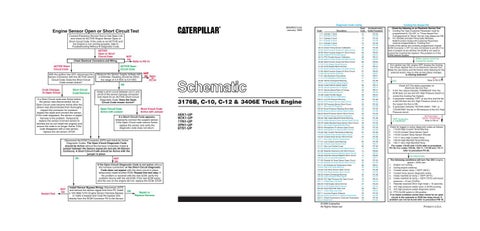
Engine Sensor Open or Short Circuit Test Connect Electronic Service Tool to Cab Data Link and check for ACTIVE Engine Sensor Open or Short Circuit Code. If the code is not ACTIVE and the Engine is not running properly, refer to Troubleshooting Without A Diagnostic Code. ACTIVE Open or Short Circuit Code
NOT OK
Check Electrical Connectors and Wiring.
ACTIVE Open Circuit Code
ACTIVE Short Circuit Code With the ignition key OFF, disconnect the Sensor Connector with the ACTIVE Short Circuit Code. Does the Short Circuit Code remain Active? Code Changes To Open Circuit
Refer to PB-10
Short Circuit Code Remains
If a Short Circuit code was Active before the sensor was disconnected, but an Open Circuit code became Active after the sensor was disconnected then thoroughly inspect the connector for moisture. Inspect the seals and connect the sensor. If the code reappears, the sensor or pigtail harness is the problem. Temporarily replace the sensor (connect sensor to harness but do not install into engine) and ensure the code is no longer Active. If the code disappears with a new sensor, replace the old sensor. STOP.
Measure the Sensor Supply Voltage with a Voltmeter. Reading should be within the range of 4.5 VDC to 5.5 VDC.
NOT OK Refer to PC-34
OK Install a short circuit between pin-C and pin-B of the sensor harness connector and check for an ACTIVE Short Circuit Diagnostic Code. Does the Open Circuit Code remain Active? Open Circuit Code Active with Jumper
Short Circuit Code Active with Jumper
If a Short Circuit Code appears, temporarily connect the suspect sensor. If the Open Circuit code returns Active, replace the sensor and verify the diagnostic code does not return.
Disconnect the ECM Connector J2/P2 and check for Active Diagnostic Codes. The Open Circuit Diagnostic Code should be Active without the harness connected. Install a jumper between the Sensor signal pin and pin-30 (Sensor Common). A Short Circuit Code should be Active with the jumper in place. OK
Restart Test
NOT OK
NOT OK If the Open Circuit Diagnostic Code is not active without the harness connected, or the Short Circuit Diagnostic Code does not appear with the short circuit in place, temporarily install another ECM. Repeat this test step. If the problem is resolved with the new ECM, verify the problem returns with the old ECM. If the new ECM works and the one on the engine did not, replace the ECM. STOP.
Install Sensor Bypass Wiring. Disconnect J2/P2 and remove the sensor signal wire from P2. Install a 125-3662 3-Pin Engine Sensor Harness Bypass, or make a bypass and route the bypass wire directly from the ECM Connector P2 to the Sensor.
OK
Repair or Replace Harness
5EK1-UP 9CK1-UP 1YN1-UP 2PN1-UP 6TS1-UP
Diagnostic Code Listing Code 1-11 2-11 3-11 4-11 5-11 6-11 22-13 26-05 26-06 30-08 30-13 40-05 40-06 41-03 41-04 51-05 51-06 71-00 71-01 71-14 84-00 84-01 84-02 84-08 84-10 84-14 91-08 91-13 100-01 100-03 100-04 100-11 102-00 102-03 102-04 102-13 105-00 105-03 105-04 105-11 108-03 108-04 110-00 110-03 110-04 110-11 111-01 111-02 111-11 121-05 121-06 122-05 122-06 168-02 171-03 171-04 171-11 174-00 174-03 174-04 190-00 190-02 228-03 231-11 232-03 232-04 244-02 249-11 252-11 253-02 253-11 254-12
Description
Flash Code
Troubleshooting Guide Procedure
Cylinder 1 Fault Cylinder 2 Fault Cylinder 3 Fault Cylinder 4 Fault Cylinder 5 Fault Cylinder 6 Fault Check Timing Sensor Calibration Multi-Function Output #1 Open Circuit Multi-Function Output #1 Short Circuit Invalid PTO Throttle Signal PTO Throttle Sensor Calibration Multi-Function Output #2 Open Circuit Mulit-Function Output #2 Short Circuit 8 Volt Supply Above Normal 8 Volt Supply Below Normal Multi-Function Output #3 Open Circuit Multi-Function Output #3 Short Circuit Idle Shutdown Override Idle Shutdown Occurrence PTO Shutdown Occurrence Vehicle Overspeed Warning Loss of Vehicle Speed Signal Invalid Vehicle Speed Signal Vehicle Speed Out of Range Vehicle Speed Rate of Change Quick Stop Occurrence Invalid Throttle Signal Throttle Sensor Calibration Low Oil Pressure Warning Oil Pressure Sensor Open Circuit Oil Pressure Sensor Short Circuit Very Low Oil Pressure Boost Pressure Reading Stuck High Boost Pressure Sensor Open Circuit Boost Pressure Sensor Short Circuit Boost Pressure Sensor Calibration High Intake Manifold Temp Warning Intake Manifold Temp Sensor Open Circuit Intake Manifold Temp Sensor Short Circuit Very High Intake Manifold Temp Atmospheric Pr Sensor Open Circuit Atmospheric Pr Sensor Short Circuit High Coolant Temperature Warning Coolant Temp Sensor Open Circuit Coolant Temp Sensor Short Circuit Very High Coolant Temperature Low Coolant Level Warning Coolant Level Sensor Fault Very Low Coolant Level Retarder Solenoid Lo/Hi Open Circuit Retarder Solenoid Lo/Hi Short Circuit Retarder Solenoid Med/Hi Open Circuit Retarder Solenoid Med/Hi Short Circuit Low or Intermittent Battery Outside Air Temp Sensor Open Circuit Outside Air Temp Sensor Short Circuit No Ambient Air Temperature Data High Fuel Temp Warning Fuel Temp Sensor Open Circuit Fuel Temp Sensor Short Circuit Engine Overspeed Warning Loss of Engine RPM Signal A/C High Pressure Sw Open Circuit J1939 Data Link Fault 5 Volt Supply Above Normal 5 Volt Supply Below Normal Event Recorder Data Lost J1922 Data Link Fault Incorrect Engine Software Check Customer or System Parameters Check Transmission Customer Parameters ECM Fault
72 72 73 73 74 74 42 69 69 29 29 66 66 21 21 67 67 01 47 47 41 31 36 36 36 00 32 28 46 24 24 46 25 25 25 42 64 38 38 64 26 26 61 27 27 61 62 12 62 14 14 14 14 51 00 00 00 65 13 13 35 34 19 58 21 21 02 58 59 56 56 53
PC-33 PC-33 PC-33 PC-33 PC-33 PC-33 PC-32 PB-25 PB-25 PB-12 PB-12 PB-25 PB-25 PB-12 PB-12 PB-25 PB-25 PB-21 PB-21 PB-21 PC-36 PB-14 PB-14 PB-14 PB-14 PB-36 PB-12 PB-12 PC-36 PC-35 PC-35 PC-36 PC-35 PC-35 PC-35 PC-37 PC-36 PC-35 PC-35 PC-36 PC-35 PC-35 PC-36 PC-35 PC-35 PC-36 PC-36 PB-17 PC-36 PB-20 PB-20 PB-20 PB-20 PB-11 PC-35 PC-35 PB-21 PC-36 PC-35 PC-35 PC-36 PC-31 PB-18 PB-24 PC-34 PC-34 PB-11 PB-24 PC-30 PC-30 PC-30 PC-30
©1999 Caterpillar All Rights Reserved
Cooling Fan Always ON Check the following on an Electronic Service Tool: 1. Cooling Fan Type Customer Parameter must be programmed to "On-Off" or "Three Speed Fan". If programmed to "None" the fan may always be ON. 2. For AUG96 and later Personality Modules, Multi-Function Output #4 Customer Parameter must be programmed to "Cooling Fan". If both of the above are correctly programmed, inspect ECM Connector J1/P1 for wire connected to pin-28. If no wire is present at pin-28 then the ECM is not used to control the Cooling Fan System. The problem is in the OEM Vehicle System. ECM is used to control the Cooling Fan System
Turn ignition key ON, engine OFF. Access the Cooling Fan Driver Special Test on an Electronic Service Tool. Make the test Active and Not Active while listening for the solenoid and/or relay to click as test status changes. Is clicking detected? NO Refer to PB-18
YES
1.
2. 3.
Check A/C Fan status parameter on Electronic Service Tool. If A/C Fan status indicates "DISABLED" then the ECM does not use and A/C High Pressure Switch to control the Cooling Fan System. If parameter indicates "OFF" at any time and the fan is still ON then the A/C High Pressure circuit is not the reason the Fan is ON. If parameter indicates "ACTIVE DIAG", "ON", or "COUNTING" the fan is ON because of the A/C High Pressure circuit. "OFF" at any time or "DISABLED"
"ACTIVE DIAG", "ON"Or "COUNTING" Refer to PB-18
Check for logged or active diagnostic codes as follows: 1. 110-00 High Coolant Temp Warning 2. 110-03 Coolant Temp Sensor Open 3. 110-04 Coolant Temp Sensor Shorted 4. 110-11 Very High Coolant Temp 5. 105-00 High Manifold Temp Warning 6. 105-11 Very High Manifold Temp For codes 110-03 and 110-04 refer to procedure PC-35. For codes 105-00, 105-11, 110-00 and 110-11 refer to procedure PC-36. No Listed Codes
The following conditions will turn Fan ON if engine speed < 2250 rpm: 1. Engine not running. 2. During engine cranking. 3. Coolant sensor temp > 205°F (96°C). 4. Coolant temp sensor diagnostic active. 5. Intake manifold air temp > 189°F (87°C). 6. Intake manifold air temp > 162°F (72°C) with boost pressure > 10 psi (70 kPa). 7. Retarder solenoid ON in high mode > 10 seconds. 8. A/C high pressure switch open or ECM counting. 9. A/C high pressure switch diagnostic active. 10. PTO On/Off switch in ON position. If no listed condition exists then check for an open circuit in the solenoid or ECM fan relay circuit. If problem can not be found refer to procedure PB-18.
Printed in U.S.A.