6
5
4
3
2
1
SENR6993 January 1995
24
26
D
D
29
27
23
43
22
C
C
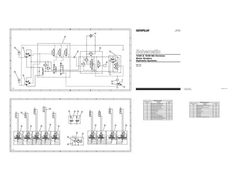
143H & 163H NA Versions Motor Graders Hydraulic Systems
19
5AK1-UP 1AL1-UP B
B
29
28
21
A
A
20
2 D14494
Printed in U.S.A.
© 1995 Caterpillar All Rights Reserved
6
5
7
4
3
5
6
2
4
3
1
2
1
Attachment Circuits Machine Location Item No.
D
D 39 40
40
41
41
38
C
C
32
33
36
37
C2
C1
35 34
31
30
34
B
B
25 43 S2 V1
44
M 42 A
S1
T1
A
T2
D14495
7
6
5
4
3
2
1
Component Description
Schematic Location
All Wheel Drive Circuit
25
Check Valve for Supplemental Steering
B-4
30
Plow/Dozer Control Valve With Float
C-1
Machine Location Item No.
31
Plow/Dozer Control Valve Without Float
C-1
2
Piston Pump For Implements And Steering
32
Snow Wing Toe Tilt Control Valve
C-2
19
Pressure Transducer
Component Description
33
Snow Wing Heel Lift Control Valve
Gear Pump For All Wheel Drive Charge
34
Blade Lift Control Valve Without Float
Schematic Location A-1 B-2
C-3
20
C-5, C-7
21
Charge Oil Filter
A-1
Piston Pump
C-2
A-1
35
Scarifier Control Valve
C-5
22
36
Plow Angle Control Valve
C-6
23
Flushing Valve
C-2
37
Ripper Control Valve
C-6
24
Hydraulic Oil Cooler
D-2
D-7
38
Ripper Cylinder
26
Control Valve
39
Scarifier Control Valve
D-5
27
Piston Motor
C-6
40
Accumulators For the Blade Cushion
D-3, D-4
28
Piston Motor
41
Mounting Valves For the Blade Cushion
D-3, D-4
29
Accumulators
A-6 B-6,C-6
43
Check Valve For All Wheel Drive Circuit
42
Check Valve for Supplemental Steering
A-4
43
Electric Drive Pump For Supplemental Steering
B-3
44
Relief Valve For Supplemental Steering
B-4
D-4
C-3