Description
Wire Number
PK
Beacon
Alarm - Action
A-14
C
Motor - Rear Washer
K-11
D
RD
Headlamp Breaker To Headlamp SW
604
OR
Stop Lamp
Alarm - Backup
L-18
2
Motor - Rear Wiper
C-11
D
YL
Turn Lamp - LH
Alternator
J-13
3
Motor - Secondary Steering
J-12
10
GY
Turn Lamp - RH
Antenna - AM/FM Radio
Fuel Level Sender
103
RD
Tail Lamps/Panel Lamps
605
0248
Data Link
105
RD
Key SW
606
Action Lamp
0615
Position Sensor (Articulation Angle)
0819
Display Data Link
0821
Display Power Supply
106 108 109
Electronic Engine Control System (MID No. 036) CID
Component
Machine Location 11
603
Speed Sensor (Ground)
0324
Component Motor - Rear Defroster
Schematic Location C-11
Bat (+)
0096
Action Alarm
Machine Location 1
RD
0084
Sensor Power Supply
Air Dryer
Schematic Location K-13
101 102
0271
Component
Description Lighting Circuits (cont'd)
Power Circuits
Component
0263
Wire Color
RD RD RD
608
Battery #1 To Battery #2
609
Dome Lamp Alt Output (+) Term.
610
GN YL OR
Flood Lamp - Rear Flood Lamp - Snow Wing Headlamp Dimmer SW
112
PU
Main Power Relay Output
611
PU
Head Lamp (High)
113
OR
Opr Mon Panel B (+) Switched
612
GY
Aux Backup Lamp
114
RD
Warning Horn (Forward)
614
PU
Tail Lamps
115
RD
Lightbar Worklamp Breaker /Turn/Hazard/Breaker
615
YL
Cab Floodlamps Relay
116
BR
Floodlamp SW
617
BR
LH Position Lamps Relay
Aux Backup Lamp
618
YL
RH Position Lamps Relay
C-3
4
Motor - Starter
J-14
12
Arc Suppressor AC Clutch
G-14
5
Power Port - 12V
B-3
14
Arc Suppressor Differential Unlock
K-16
6
Radio - AM/FM
C-3
15
Batteries - 12 Volt
I-13
7
Radio - AM/FM Cassette
C-3
15
Beacon
C-11
4
Receptacle - Aux. Start
K-13
1
Beacon - Open Rops
C-15
4
Relay - Aux. Backup Lamp
D-7
16
Block - B+ Junction
I-13
7
Relay - Cab Floodlamps
K-8
B
Breaker - Alternator
H-13
7
Relay - LH Position Lamp
K-8
B
Breaker - Engine Control
G-13
7
Relay - Main
H-13
7
Breaker - Headlamp
G-13
7
Relay - Position Lamp Coupler
J-8
B
Breaker - Ltbar Worklamp/Hazard/Turn/Panel
G-13
7
Relay - RH Position Lamp
J-8
B
0001
Injector Cylinder Solenoid #1
117
YL
0002
Injector Cylinder Solenoid #2
118
GY
Front Wipers
619
GN
Head Lamp (Low)
H-13
Relay - Secondary Steering
J-13
12
Injector Cylinder Solenoid #3
Breaker - Main
7
0003
119
PK
Rear Wipers
629
PK
Lightbar Worklamp
0004
Injector Cylinder Solenoid #4
Cap - Service Tool Connector
A-11
C
Relay - Start Aid
L-13
1
120
YL
Cab Floodlamps Relay
633
BU
Moldboard Lamps
Control - Engine ECM
I-18,D-18
8
Relay - Starter
G-13
7
122
BU
Air Dryer
647
GN
Aux Backup Lamp SW
Control - Secondary Steering
124
GN
A/C
668
BU
Headlamp SW
Control - Transmission
685
BR
Blade Floodlamps
0005
Injector Cylinder Solenoid #5
0006
Injector Cylinder Solenoid #6
0041
ECM 8 Volt DC Supply
0091
Throttle Sensor
126
PK
XMSN Control
OR
Park Brake Solenoid
A-16
E
Relay - Tail/Panel Lamps
K-8
B
D-14,F-14
E
Resistor - Front Defroster
C-2
24
Converter - 24V To 12V (Comm. Radio)
D-3
D
Resistor - Heater/AC
B-16
E
Converter - 24V TO 12V (Entertain. Radio)
L-9
9
Resistor - Panel Lamp
K-4
B
Not Used
Converter - 24V TO 12V (Power Port)
L-11
9
Resistor - Rear Defroster
C-10
11
Not Used
Diode - Floodlamps Coupler
J-8
B
Resistor - Secondary Steering
K-13
12
GN
Secondary Steering Motor Relay
Diode - Moldboard Lamp
E-9
10
Sender - Articulation Angle
H-11
17
728
BU
Primary Steering Pressure SW
Diode - Snow Wing Lamp
E-9
10
Sender - Coolant Temperature
I-14
3
Secondary Steering Control
751
GN
XMSN Shift Solenoid #3
Diode - LH Turn Indicator
L-2
A
Sender - Fuel Level
G-14
8
Secondary Steering Motor
752
YL
XMSN Shift Solenoid #1
Diode - RH Turn Indicator
L-2
A
Sender - Fuel Temperature
J-16
8
BU
XMSN Shift Solenoid #2
Flasher
K-8
B
Sender - Intake Air Temperature
J-15
18
OR
XMSN Shift Solenoid #8
Fuse Block - Overhead
C-4,C-5
11
Sensor - Atmospheric Pressure
J-15
18
Not Used
Fuse Block - Switched Power
J-5
B
Sensor - Cam Speed Timing
I-15
5
Fuse Block - Unswitched Power
J-7
B
Sensor - Crank Speed Timing
I-15
19
Fuses - Overhead
C-5
11
Sensor - Engine Oil Pressure
I-16
8
Fuses - Switched Power
I-4
B
Sensor - Fan Drive Pressure
J-18,K-18
2
Fuses - Unswitched Power
I-6
B
Sensor - Fuel Pressure
J-15
8
Gauge - LH Air Pressure
G-1
A
Sensor - Inching Pedal Position
F-6
20
Gauge - RH Air Pressure
G-1
A
Sensor - Throttle Position
K-9
13
Ground - Cab Boss 2 (Cab Front)
B-7
A
Sensor - Turbo Outlet Pressure
J-15
18
Ground - Cab Boss 3 (Upper Cab)
D-3
15
Sensor - XMSN Input Speed
B-18
21
Ground - Engine Block Boss (RH Side)
J-14
12
Sensor - XMSN Output Speed Sensor #1
B-18
21
Ground - Front Frame Boss 2 (LH Side)
I-9
20
Sensor - XMSN Output Speed Sensor #2
A-18
21
0094
Fuel Pressure Sensor
127
Control Circuits
0100
Oil Pressure Sensor
129
RD
Lighter
718
BU
0110
Engine Coolant Temperature Sensor
130
RD
Stop Lamp Pressure SW
719
GY
0168
Electrical System Voltage
134
RD
Secondary Steering Test SW
727
0172
Inlet Air Temperature Sensor
135
BU
12V Power Port
0174
Fuel Temperature Sensor
136
GN
0190
Engine Speed Signal
0248
CAT Data Link
137
RD
0253
Personality Module Mismatch
141
PK
Front Defroster SW
754
0254
Engine ECM
144
GN
Beacon SW
755
0261
Engine Speed Sensor
147
RD
24V To 12V Converter (Aux Power Port)
796
BR
0262
5 Volt Sensor Supply
148
WH
Snow Wing Lamp SW
797
PU
Not Used
0267
Engine Shutdown Switch
149
PU
Floodlamp SW
A701
GY
Fuel Injector #1
0268
Programmable Parameters
150
RD
Engine Control Breaker
A702
PU
Fuel Injector #2
0273
Turbo Outlet Pressure Sensor
151
GN
Rear Defroster SW
A703
BR
Fuel Injector #3
0274
Atmospheric Pressure Sensor
0290
Fan Drive Pressure Sensor
155
PK
Not Used
A704
GN
Fuel Injector #4
160
PU
Heated Mirrors SW
A705
BU
Fuel Injector #5
0291
Fan Drive Solenoid
0296
Unable to Communicate with Transmission ECM
162
YL
Moldboard Lamp SW
A706
GY
Fuel Injector #6
0297
Unable to Communicate with All Wheel Drive ECM
165
YL
Differential Lock SW
A746
PK
Turbo Outlet Pressure Sensor
0342
Cam Speed Timing Sensor
169
PK
Blade Cushion SW/Centershift Pin SW
A747
GY
ATM Pressure Sensor
0545
Start Aid Relay
170
RD
Product Link (Connector #24)
A751
YL
Fuel Temperature Sender
E-9
Sensor - XMSN Temperature
B-17
29
Throttle Lock Indicator Lamp
Ground - Front Frame Boss 3 (LH Side)
10
0548
173
RD
Turn Signal SW/Flasher
A755
PK
Throttle Speed Set SW
0549
Throttle Lock Switch
Ground - Platform Boss 2
J-11
10
Shifter - XMSN
A-12
C
176
RD
24V To 12V Converter (Communication Radio)
E708
PK
Opr Mon Display Module Clock
Ground - Rear Frame Boss 2 (RH Side)
H-12
12
Solenoid - AC Clutch
H-15
5
177
RD
Main Breaker
E735
PU
Operator Mode SW
Ground - Rear Frame Boss 3 (LH Side)
K-15
8
Solenoid - Blade Cushion #1
I-5
22
179
RD
24V To 12V Converter (Entertainment Radio)
F715
PU
Ground Level Shutdown SW (N/O)
Ground - Rear Frame Boss 5 (RH Side)
F-12
12
Solenoid - Blade Cushion #2
I-4
22
185
YL
Not Used
F716
WH
Ground Level Shutdown SW (N/C)
Ground - Service Center Boss 1 (LH Side)
K-14
1
Solenoid - Centershift Pin
E-7
23
F762
GY
Start Aid Relay
Ground - Service Center Boss 2 (RH Side)
K-14
7
Solenoid - Differential Unlock
K-16
6
0562
Unable to Communicate with CAT Monitoring System
0600
Hydraulic Oil Temperature
Electronic Transmission Control System (MID No. 081) CID
Ground Circuits
Component
0168
Electrical System Voltage
200
BK
Main Chassis
F775
BU
Centershift Pin Solenoid
Ground Strap - Articulation Joint
J-10
17
Solenoid - Ether Start Aid
K-13
1
0177
Temperature Sensor (Transmission Oil)
201
BK
Operator Monitor Panel
H746
YL
Fan Drive Solenoid
Ground Strap - Engine Block To Engine ECM
D-18
8
Solenoid - Forward Horn
F-7
13
0248
CAT Data Link
202
BK
XMSN Control
H747
BR
Fan Drive Solenoid Return
Ground Strap - Platform To Cab
K-11
17
Solenoid - Fuel Injector #1
J-18
18
0268
Programmable Parameter
205
BK
Console/Panel
J700
BR
Not Used
Ground Strap - Platform To XMSN Control
D-14
13
Solenoid - Fuel Injector #2
J-18
18
0444
Magnetic Switch (Start Relay)
206
BK
Battery #1 To Master Disconnect SW
J701
GN
Not Used
Group - A/C
B-16
E
Solenoid - Fuel Injector #3
I-18
18
0520
Configuration (Transmission)
210
BK
AM/FM Radio
J702
BK
Air Inlet Heater Return
Group - Heater
B-16
E
Solenoid - Fuel Injector #4
I-18
18
0562
Caterpillar Monitoring System
229
BK
Product Link (Connector #24)
J764
BR
Autoshift SW
Group - Light Duty Heater
0573
Position Sensor (Inching Pedal) Speed Sensor (Transmission Output) (No. 1)
BK
Engine ECM (Solenoid Return)
J765
BU
Inching Pedal Limit SW
Heater - Jacket water
0585
232
Backup Alarm
290
BK
Caterpillar Monitoring System (Service)
J766
PU
Brake Pedal Limit SW
Jumper Plug - Secondary Steering
0637 0668
Transmission Control (Shift Lever)
291
BK
Caterpillar Monitoring System (Clear)
K748
OR
Secondary Steering Resistor
0669
Speed Sensor (Transmission Input)
A287
BK
Engine ECM Control
823
GN
Not Used
0673
Speed Sensor (Transmission Output) (No. 2)
C203
BK
Not Used
892
BR
(-) Cat Data Link
0674
Speed Sensor (Intermediate Transmission) (No. 1)
0675
Speed Sensor (Intermediate Transmission) (No. 2)
0868
Indicator Lamp (Automatic Shift)
1401
Solenoid Valve (Forward High)
1402
Solenoid Valve (Forward Low)
1403
Solenoid Valve (Reverse)
1404
Solenoid Valve (Speed Clutch) (No. 2)
1405
Solenoid Valve (Speed Clutch) (No. 3)
1406
Solenoid Valve (Speed Clutch) (No. 1)
1407
Solenoid Valve (Low Range)
403
1408
Solenoid Valve (High Range)
1484
Limit Switch (Inching Pedal)
1580
Indicator Lamp (Transmission Filter)
Basic Machine Circuits
893
GN
(+) Cat Data Link
304
WH
Starter Relay No. 1 Output
F842
BU
AIH Indicator Lamp
306
GN
Starter Relay Coil
F843
YL
Inching Pedal Position Sensor
307
OR
Key Start SW
G828
WH
Pressure Sensor (Power)
308
YL
Main Power Relay Coil
G829
BR
Pressure Sensor (Return)
321
BR
Backup Alarm
G833
PK
Temperature Sensor (Return)
322
GY
Warning Horn (Forward)
G850
BU
Air Inlet Heater
Monitoring Circuits
G856
WH
(+) TDC Probe
B-16
E
Solenoid - Fuel Injector #5
I-18
18
H-15,I-15
12
Solenoid - Fuel Injector #6
I-18
18
A-15
E
Solenoid - Hydraulic Fan
K-9
31
Lamp - Action
J-1
A
Solenoid - Parking Brake
E-6
13
Lamp - AIH Indicator
K-1
A
Solenoid - XMSN (1st)
C-18
29
Lamp - Autoshift Indicator
J-1
A
Solenoid - XMSN (2nd)
C-18
29
Lamp - Centershift Pin Indicator
K-1
A
Solenoid - XMSN (3rd)
C-18
29
Lamp - Differential Lock Indicator
K-1
A
Solenoid - XMSN (Forward High)
D-18
29 29
Lamp - Dome
C-3
15
Solenoid - XMSN (Forward Low)
D-18
Lamp - Hazards Indicator
L-1
A
Solenoid - XMSN (High Range)
C-18
29
Lamp - High Beam Indicator
K-1
A
Solenoid - XMSN (Low Range)
C-18
29
Lamp - HVAC Panel
C-16
C
Solenoid - XMSN (Reverse)
D-18
29
Lamp - LH Blade Floodlamp
G-4
20
Speaker - Left Hand
D-2
24 16
Lamp - LH Cab High Beam Headlamp
C-2
24
Speaker - Right Hand
B-2
Lamp - LH Cab Low Beam Headlamp
C-2
24
Switch - AC Pressure
G-15
5
Lamp - LH Cab Position
D-2
24
Switch - Autoshift
C-11
C
GN
Alternator (R) Term.
G857
YL
(-) TDC Probe
404
YL
Opr Mon Hydraulic Temperature
G858
OR
Not Used
Lamp - LH Cab Turn Signal
C-2
24
Switch - Aux Backup Lamp
A-7
11
408
WH
Opr Mon Brake System Pressure
J844
GY
Analog Sensor (Power)
Lamp - LH High/Low/Position/Turn
F-1
25
Switch - Beacon
B-10
30
410
WH
Opr Mon Action Alarm
R800
OR
Digital Sensor (Power)
Lamp - LH Inner Cab Floodlamp
D-2
24
Switch - Blade Cushion
C-12
C
¹ The CID is a diagnostic code that indicates which component is faulty.
411
PK
Opr Mon Action Lamp
900
PU
XMSN Shift Solenoid #4
Lamp - LH Lightbar High Beam Headlamp
F-1
25
Switch - Blower (Heater/AC)
C-16
C
² The MID is a diagnostic code that indicates which electronic control module diagnosed the fault.
417
GY
Opr Mon Primary Steering Pressure
901
WH
XMSN Shift Solenoid #6
Lamp - LH Lightbar Low Beam
F-1
25
Switch - Brake Pedal Limit
F-6
B
419
YL
Opr Mon Parking Brake
902
BR
XMSN Shift Solenoid #5
Lamp - LH Lightbar Turn Signal
F-1
25
Switch - Centershift Pin
C-12
C
426
BR
XMSN Filter Bypass
903
GY
XMSN Shift Solenoid #7
Lamp - LH Lightbar Worklamp
F-3
25
Switch - Centershift Pin Indicator
E-6
432
PK
Service Brake SW (Engine ECM)
911
YL
Not Used
Lamp - LH Moldboard
I-4
22
Switch - Differential Lock
439
YL
Centershift Pin Indicator
921
WH
Solenoid Return #1 (XMSN)
Lamp - LH Outer Cab Floodlamp
D-2
24
Switch - Ether Start Aid Range
Solenoid Return #2 (XMSN)
Lamp - LH Rear Floodlamp
L-13
27
L-18 L-18
Failure Mode Identifiers (FMI)¹ FMI No.
Failure Description
0
Data valid but above normal operational range.
1
Data valid but below normal operational range.
2
Data erratic, intermittent, or incorrect.
3
Voltage above normal or shorted high.
4
Voltage below normal or shorted low. Current below normal or open circuit.
5
447
PK
Fuel Level Gauge
922
BR
30
Switch - Front Upper Wiper (NOTE C)
B-9
30
Lamp - RH Blade Floodlamp
G-4
13
Switch - Ground Level Shutdown
D-17
29
Lamp - RH Cab Low Beam Headlamp
B-2
16
Switch - Headlamp
L-3
B
BR
Speed Set/Accel
12
Bad device or component.
13
Out of calibration.
G434
BU
Hydraulic Oil Temperature (Engine ECM)
C979
OR
Speed Resume/Decel
14
Parameter failures.
G460
GN
XMSN Temperature Sensor
C991
PK
Fuel Pressure Sensor (Signal)
15
Parameter failures.
Accessory Circuits
E900
WH
(+) XMSN Output Speed Sensor 1
¹The FMI is a diagnostic code that indicates what type of failure has occurred.
Event Codes For Engine ECM Event Code
Condition
Lamp - RH Cab Position
B-2
16
Switch - Headlamp Dimmer
K-4
B
Lamp - RH Cab Turn Signal
B-2
16
Switch - Heated Mirrors
B-7
11
Lamp - RH High/Low/Position/Turn
F-1
26
Switch - Heater Thermostat
C-16
E
Lamp - RH Inner Cab Floodlamp
B-2
16
Switch - Horn
K-7
B
Lamp - RH Lightbar High Beam Headlamp
F-1
26
Switch - Hydraulic Temperature
E-6
17
Lamp - RH Lightbar Low Beam
E-1
26
Switch - Inching Pedal Limit
G-6
B
Lamp - RH Lightbar Turn signal
F-1
26
Switch - Key
A-15
C
Lamp - RH Lightbar Worklamp
F-3
26
Switch - LH Brake System Pressure
F-6
31
28
Switch - Moldboard Lamps
B-7
11
504
YL
Wiper - Rear (Low)
E905
BU
(-) XMSN Int Speed Sensor 2
Lamp - RH Rear Turn Signal
A-18
28
Switch - Open Rops Beacon
C-15
4
505
BU
Wiper - Rear (HI)
E906
OR
(+) XMSN Output Speed Sensor 2
Lamp - RH Stop/Taillight
A-18
28
Switch - Operator Mode
L-1
A
CONN 27
506
PU
Washer - Front Upper
E907
GY
(-) XMSN Output Speed Sensor 2
Lamp - RH Turn Indicator
K-1
28
Switch - Panel Lamp Dimmer
L-4
B
CONN 28
G-12
12
507
WH
Washer - Rear
E908
BR
(+) XMSN Input Speed Sensor
Lamp - Shift Lever Panel
B-12
C
Switch - Parking Brake Pressure
E-10
32
CONN 29
I-12
20
508
PU
Radio Speaker - Left
E909
WH
(-) XMSN Input Speed Sensor
Lamp - Snow Wing
E-5
11
Switch - Primary Steering Pressure
L-9
9
CONN 30
I-12
20
WH
Radio Speaker - Left (Common)
E937
PU
Redundant Neutral
Lamp - Throttle Lock Indicator
L-1
A
Switch - Rear Defroster
A-10
C
CONN 31
I-12
20
CONN 32
L-12
32
CONN 33
L-12
1
CONN 34
L-11
9
A-11
C
E053
Low Fuel Pressure Warning
Blower Motor (Low)
E942
E096
High Fuel Pressure Warning
521
YL
A/C SW To Refrigerant SW
E943
E100
Low Engine Oil Pressure Warning
522
E190
Engine Overspeed Warning
537
GN
Turn Signal SW To Flasher
E945
PU
Eighth Gear
538
BR
Hazard Indicator Lamp
E946
OR
Forward Direct
Trip Odometer
6
Trip Fuel
7
Reset Trip Values
WH
A/C Clutch To Thermostat SW
E944
13 11
30
32
26
L-1
A
Switch - Rear Wiper
A-9
30
C
Switch - RH Brake System Pressure
E-6
31
Mirror - LH Heated
D-1,E-2
24
Switch - Secondary Steering Test
C-12
C
Fourth Gear
Mirror - RH Heated
D-1,E-2
16
Switch - Snow Wing Lamp
A-7
11
CONN 36
A-10
30
GN
Fifth Gear
Module - Caterpillar Monitoring System
I-1
A
Switch - Stop Lamp Pressure
F-7
31
CONN 37
C-10
11
BR
Sixth Gear
Module - Quad Gauge
H-1
A
Switch - Tail Lamp
L-4
B
CONN 38
C-10
4
Module - Speedo/Tach
H-1
A
Switch - Throttle Hold Mode
B-11
C
CONN 39
C-10
4
Motor - Blower (Heater/AC)
B-15
E
Switch - Throttle Speed Set
A-11
C
CONN 40
C-10
11
L-8
B
CONN 41
C-10
11
K-13
1
CONN 42
D-10
A
CONN 43
E-10
A
CONN 44
E-10
A
CONN 45
L-9
9
CONN 46
C-9
11
CONN 47
C-9
11
CONN 48
C-8
11
CONN 49
C-8
11
CONN 50
K-7
B
CONN 51
G-6
20
CONN 52
G-6
13
CONN 53
H-6
13
CONN 54
H-6
20
CONN 55
I-6
20
CONN 56
I-6
13
CONN 57
I-6
13
GY
Seventh Gear
539
BU
RH Turn Indicator Lamp
E947
WH
Reverse Direct
540
WH
LH Turn Indicator Lamp
E948
BU
Park
556
WH
Differential Lock SW
E949
YL
Neutral
567
WH
Front Defrost SW
E963
BK
(-) Crank Speed
Motor - Front Defroster Fan
C-2
24
Switch - Turn Signal
Motor - Front Lower Washer
L-11
A
Switch - XMSN Filter Bypass
Motor - Front Lower Wiper
G-4
A
Motor - Front Upper Washer
L-11
A
Motor - Front Upper Wiper
PK
Rear Defrost SW
E964
WH
(+) Crank Speed
570
BU
Blade Cushion Solenoid
E965
BU
(-) Cam Speed
575
YL
Wiper - Front Lower (Park)
E966
YL
(+) Cam Speed
576
PK
Wiper - Front Lower ( Low)
E974
GN
Inching Pedal Limit SW (N/C)
4
A
D-3
15 11
C = Operator's compartment (Right side console).
Wiper - Front Lower (High)
G939
PK
Not Used
D = Operator's compartment (Headliner).
BU
Wiper - Front Lower (Wash)
G946
OR
Throttle Hold Indicator
E = Operator's compartment (Under seat).
589
GN
A/C Clutch Solenoid
K917
BR
Fan Drive Pressure Sensor (Signal)
592
BU
24V To 12V Converter (Entertainment Radio)
K927
BU
Not Used
A503
PK
Front Defrost Fan (Low)
L983
WH
Injector 1 & 2 (Return)
A504
GN
Rear Defrost Fan (Low)
L984
OR
Injector 3 & 4 (Return)
A506
OR
Front Defrost Fan (High)
L985
YL
Injector 5 & 6 (Return)
A507
YL
Rear Defrost Fan (High)
L987
WH
Ether Start Aid SW
14
27
Component Description
Resistance (Ohms)¹
PK
24V To 12V Converter (Entertainment Radio)
M998
OR
Autoshift Indicator Lamp
3E-1906
Solenoid - AC Clutch
Turn Signal Indicator/Flasher
R914
OR
Throttle Hold Mode SW
3E--6332
Solenoid - Start Aid
C542
GN
Heated Mirrors SW
R993
BR
Not Used
3E-7842
Resistor - Secondary Steering
150 ± 7.5
7T-4003
Resistor - Front & Rear Defrost
10 ± .5
9G-1950
Resistor - AC/Heater Blower Motor
BR
Digital Sensor (Return) Throttle Hold (OFF)
601
GY
Panel Lamp (High)
T993
BR
Analog Sensor Return
112-2240
17.6 ± 0.6
23
Solenoids - Blade Cushion (No. 1 & No. 2)
31 20 13
8 12
2
19
6
21
22
C
Resistor, Sender and Solenoid Specifications Part No.
A 25
18
E
PU
OR
B
5 3
A541
T914
30
1
28
7
A513
R998
16
B = Operator's compartment (Steering Console).
PU
Panel Lamp (Low)
D
A = Operator's compartment (Dash).
578
BR
24
Some components listed are ONLY in VOLUME 1 or ONLY in VOLUME 2.
577
600
CONN 35
Machine locations are repeated for components located close together.
569
Lighting Circuits
C
28
A-15
9
6
10 32
Part No.
Machine
Code
140H
40
140H¹
41
160H
3E-2026
3E-5464
Function Brake Air Pressure (Stop Lamp)
Thermostat
60
160H¹
61
3E-6450
Primary Steering Pressure
Form Number
Alternator:
200-2232
Electric Starting Motor:
165-4619
131-4135
60 kPa MAX
38 ± 20 kPa
(8.7psi MAX)
(5.5 ± 2.9 psi)
Normally Open
SENR3581 RENR5740
Engine Control Monitor:
SENR9515
Starting and Charging:
SENR2947
Transmission Electronic Control:
RENR4104
180-5462
G-4
13
G-4
20
32.6 ± 1.6
CONN 66
H-4
20
CONN 67
I-4
22
CONN 68
I-4
22
CONN 69
I-4
22
CONN 70
H-3
A
CONN 71
H-3
A
CONN 72
C-2
24
17
8.7 ± 0.4 1.06 ± 0.05
148-2350
Solenoid - Hydraulic Fan
5.0 ± 0.3
CONN 73
C-2,D-2
24
152-8346
Solenoid - Centershift Pin
32.6 ± 1.6
CONN 74
D-2,E-2
16
239 To 255
CONN 75
D-2,E-2
24
25 To 29
CONN 76
H-2
A
CONN 77 (VOLUME 2 ONLY)
A-18
28
CONN 78 (VOLUME 2 ONLY)
L-18
2
CONN 79 (VOLUME 2 ONLY)
L-18
27
CONN 80 (VOLUME 2 ONLY)
I-6
20
174-3705
Solenoid - Differential Unlock
32.6 ± 1.6
A-C, Normally Closed
186-1526
Solenoids - XMSN (1st,2nd,3rd,High Range, and Low Range)
31.3 ± 3.0
(92.8 psi MAX)
(76.9 ± 5.8 psi)
102 ± 3°C
90° MIN
(215.6 ± 5.4°F)
(194°F MIN)
275 to 1750 kPa ¹
-
(40 to 255 psi)
-
173-2018
Sender -
Fuel Level
Empty
Fuel Level
Full
Normally Open
187-1008
Sender - Articulation Angle
Normally Closed
188-9250
² With increasing pressure the closed condition can be maintained up to 2800 kpa (405 psi), with decreasing pressure the closed condition can be maintained down to 170 kpa (25psi).
Solenoids -
Forward Horn
80° from Full CCW
10 ± 3
Mid-range
85 ± 7
80° from Full CW
185 ± 7 74.0 ± 7.4
Park Brake
Normally Open ²
¹ Contact position at the contacts of the harness connector.
15
CONN 65
A-B, Normally Open
Park Brake Pressure
15
D-4
CONN 64
700 ± 100 kPa
530 ± 40 kPa
B-4
CONN 61
Tap 1.0 ± .05
1200 kPa MAX
Normally Closed
CONN 60
Overall 2.0 ± .1
2.2 ± 0.8°c
(101.5 ± 14.5 psi)
AC Pressure
Solenoid - Fuel Injector
22
20
(36 ± 1.4°F)
SENR7508
Electronic Monitoring System:
147-0373
B
I-5
25
-1.1 ± 0.8°c
640 kPa MAX
Hydraulic Temperature
Contact Position¹
Solenoids - XMSN (Fwd High,Fwd Low,and Reverse)
CONN 59
L-5
E-4
(30 ± 1.4°F)
(174 psi MAX)
Related Electrical Service Manuals Title
Deactuate
Brake System Pressure
¹ High Ambient Temperature Model 114-9281
Actuate
145-1144
CMS Service Tool
F-4,F-3
Fuel Temperature
Off Machine Switch Specification
CONN 58
CONN 63
1000
Senders - Intake Air Temperature
26
Service Tool
CONN 62
29
Coolant Temperature 130-9811
8
Machine Codes
12
L-13
BU
5
12
G-12
Lamp - RH Rear Floodlamp
517
Trip Machine Hours
G-12
(+) XMSN Int Speed Sensor 2
YL
4
12
CONN 26
BR
E941
Cumulative Fuel
G-12
E904
Blower Motor (Medium)
3
12
CONN 25
Wiper - Rear (Park)
GN
Diagnostic Scrolling
F-12
BR
516
2
32
CONN 24
503
Low Engine Oil Pressure Derate
Digital Tachometer
13
F-12
1
E039
1
E-12,F-12
CONN 23
K-13
Third Gear
0
CONN 22
Switch - Master Disconnect
BU
Odometer
32
16
E940
Service Meter
C-13
B-2
Blower Motor (HI)
Number
1
CONN 21
Lamp - RH Outer Cab Floodlamp
GY
Operator Mode
2
L-13
(-) XMSN Int Speed Sensor 1
515
Monitoring System Operator Modes
L-14
CONN 20
YL
High Inlet Air Temperature Warning
9
CONN 19
E903
E027
Module Configuration
8
Wiper - Front Upper (HI)
High Inlet Air Temperature Derate
8
L-14
OR
E025
Calibration (Transmission Control)
8
CONN 18
502
Lighter - Cigar
7
K-14
B
Lamp - XMSN Filter Bypass Indicator
Calibration (Transmission Control)
8
CONN 17
K-4
Second Gear
6
32
H-14
Switch - Lightbar Worklamp
First Gear
Calibration (Articulation Gauge)
31
3
C-14
CONN 16
22
OR
5
23
CONN 15
I-4
WH
Units
16
32
Lamp - RH Moldboard
E939
4
18
12
A
B
E
21 7
22
C-14
(+) XMSN Int Speed Sensor 1
E938
Digital Tattletale
17
19
6
20 D
C
CONN 14
PU
Radio Speaker - Right (Common)
3
5
C
A-15
E902
Radio Speaker - Right
Diagnostic Service
8
B-15
CONN 13
Wiper - Front Upper (Low)
BR
2
1
24
CONN 12
GN
GN
Parameter Display
4
27 2 29
C
501
512
1
10
2
B-15
(-) XMSN Output Speed Sensor 1
511
Harness Code
9 14
L-16
CONN 11
GN
High Engine Coolant Temperature Warning
0
15
8 2
E901
E017
Operator Mode
25
Aux Backup Lamp
I-16 L-16
Wiper - Front Upper (Park)
509
Number
CONN 10
TDC Service Probe
BR
High Engine Coolant Temperature Derate
Service Mode
Connector Number
500
E015
Monitoring System Service Modes
CONN 9
16
C978
Parameter failures.
CONN 8
B-2
XMSN Filter Bypass Indicator
Condition not met.
30
Lamp - RH Cab High Beam Headlamp
BU
20
A-9
30
C436
19
Switch - Front Lower Wiper (NOTE B)
B-9
Inching Pedal Limit SW (N/O)
Sensor supply fault.
27
A-9
BU
18
29
Switch - Front Upper Wiper (NOTE B)
C977
Module not responding.
D-16
Switch - Front Lower Wiper (NOTE C)
Opr Mon Display Module Load
Parameter not available.
CONN 7
2
BU
17
30
27
C414
16
A-10
K-1
Throttle Lock
Failure mode not identifiable.
Switch - Front Defroster
L-18
WH
11
32
27
Lamp - License Plate
C975
Connector Location
32
Lamp - LH Turn Indicator
Opr Mon Display Module Data
Printed in U.S.A.
© 2005 Caterpillar All Rights Reserved
A-17
Throttle Speed Set SW
YL
Abnormal update. Abnormal rate of change.
1 2
Component Part Number
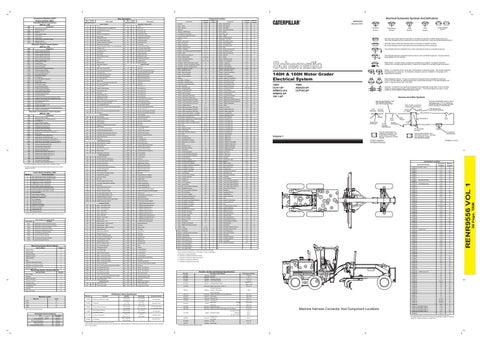
Typical representation of a Sure-Seal connector. The plug and receptacle contain both pins and sockets.
CONN 6
Coolant Temperature
C413
9 10
Volume 1
Typical representation of a Deutsch connector. The plug contains all sockets and the receptacle contains all pins.
105-9344
B
BR
Intake Air Temperature Sender (Signal)
200-L32 BK-14
K-5
BU
BU
2
Switch - Floodlamp
995
C967
Plug
Pin or Socket Number 1 2
Fuse
32
A982
Opr Mon Articulation Angle
Receptacle
A-17
Not Used
YL
Ground Circuit Connection Number Identification
Wire Gauge
CONN 5
Secondary Steering Motor Indicator
A429
Single Wire Connector
Wire Color
B
YL
Abnormal frequency, pulse width, or period.
Socket
Pin
I-8,K-8
PK
8
325-A135 PK-14
Wire, Cable, or Harness Assembly Identification Part Number For L-C12* AG-C4* Connector Assembly 3E-5179 111-7898 325-A135 PK-14 1
29
486
Throttle Hold Mode SW
* * AG-C3 C-C4 130-6795 130-6795
* Harness identification letter(s) and a serializing code. The "C" stands for connector and the number indicates which connector in the harness.
A-17
462
Throttle Position Sensor (Signal)
Harness identification code This example indicates wire 135 in harness "AG".
CONN 4
Lamp - LH Stop/Tail
BU
Harness And Wire Symbols
B
Autoshift SW
GN
Solenoid - A solenoid is an electrical component that is activated by electricity. It has a coil that makes an electromagnet when current flows through it. The electromagnet can open or close a valve or move a piece of metal that can do work.
K-5
Engine Oil Pressure
A983
160H: ASD225-UP CCP193-UP
18
YL
C912
Relay (Magnetic Switch) - A relay is an electrical component that is activated by electricity. It has a coil that makes an electromagnet when current flows through it. The electromagnet can open or close the switch part of the relay.
B-17
GY
Differential Lock Indicator
140H: CCA1-UP APM412-414 APM416-UP 126 1-UP
T
CONN 3
977
Brake System Pressure SW
140H & 160H Motor Grader Electrical System
Sender - A component that is used with a temperature or pressure gauge. The sender measures the temperature or pressure. Its resistance changes to give an indication to the gauge of the temperature or pressure.
23
994
WH
Reed Switch - A switch whose contacts are controlled by a magnet. A magnet closes the contacts of a normally open reed switch; it opens the contacts of a normally closed reed switch.
27
Opr Mon Display Module Power
WH
This indicates that the component does not have a wire connected to ground. It is grounded by being fastened to the machine.
J-17
Not Used
498
This indicates that the component has a wire connected to it that is connected to ground.
L-18
YL
488
Normally closed switch that will open with an increase of a specific condition. No circle indicates that the wire cannot be disconnected from the component.
CONN 2
PK
Mechanical system not responding properly.
Normally open switch that will close with an increase of a specific condition (temp-press-etc.). The circle indicates that the component has screw terminals and a wire can be disconnected from it.
CONN 1 (VOLUME 1 ONLY)
458
Current above normal or grounded circuit.
Circuit Breaker Symbol
Flow Symbol
Level Symbol
Temperature Symbol
Machine Location
450
7
T
Pressure Symbol
Schematic Location
Lamp - LH Rear Turn
6
RENR9556 January 2005
191-2298
Resistor - Air Dryer
194-4181
Resistor - Panel Lamp
¹ At room temperature unless otherwise noted.
8.8 To 8.7 10 ± .3
Machine Harness Connector And Component Locations
CONN 81 G-14 5 The connectors shown in this chart are for harness to harness connectors. Connectors that join a harness to a component are generally located at or near the component. See the Component Location Chart.
30 Page, TRM
CID
Wire Color
Electrical Schematic Symbols And Definitions
Component Location
Wire Description Wire Number
RENR9556 VOL 1
Component Identifiers (CID¹) Module Identifier (MID²) Caterpillar Monitoring System (MID No. 030)