Component Location
Description
Wire Color
Power Circuits
Schematic Location
Machine Location
Air Dryer
F-12
1
Description
Lighting Circuits (Continued)
Component
Schematic Location
Machine Location
Sensor - Atmospheric Pressure
G-15
76
Component
101
RD
Battery +
609
YL
Snow Wing Lamp
Alarm - Action
A-12
2
Sensor - Engine Oil Pressure
G-15
77
102
BU
Headlamps
611
PU
LH/RH Lightbar High Beam Headlamps
Alarm - Backup
J-16
3
Sensor - Engine Speed
F-15
78
103
YL
Tail/Panel Lamps
612
GY
Auxiliary Circuit
Alternator
H-12
4
Sensor - Fuel Pressure
F-12
79
105
BR
Key Switch
614
PU
Auxiliary Circuit
Arc Suppressor - Differential Lock
I-15
5
Sensor - Inching Pedal Position
E-7
80
106
WH
Battery 1 to Battery 2
617
BR
Auxiliary Circuit
Battery 1
G-12
6
Sensor - Injector Actuation Pressure
G-15
81
108
BU
Dome Lamp
618
YL
Auxiliary Circuit
Battery 2
G-12
7
Sensor - Intake Manifold Air Pressure
G-15
82
109
RD
Alternator Output +
619
GN
LH/RH Lightbar Low Beam Headlamps
Breaker - Alternator
G-12
8
Sensor - Secondary Engine Speed
F-15
83
112
PU
Main Relay Output
629
PK
LH/RH Lightbar Worklamps
Breaker - Main
G-12
9
Sensor - Throttle Position
I-8
84
113
OR
Monitor
633
BU
LH/RH Moldboard Lamps
Control - Engine
H-16
10
Sensor - Transmission Input Speed
B-16
85
114
GN
Forward Warning Horn
647
GN
Auxiliary Circuit
Control - Transmission
E-12
11
Sensor - Transmission Output Speed 1
B-16
86
115
PK
Lightbars
685
BR
LH/RH Blade Floodlamps
Converter - 12 to 24 Volt 1
J-10
12
Sensor - Transmission Output Speed 2
B-16
87
116
BR
Rear Floods
Converter - 12 to 24 Volt 2
I-8
13
Sensor - Transmission Temperature
D-15
88
117
YL
Load 1
751
GN
Transmission Solenoid 3 (Reverse)
Converter - 20A
C-2
14
Sensor - Turbo Inlet Pressure
F-12
89
118
GY
Front Upper Wiper
752
YL
Transmission Solenoid 1 (Forward High)
Flasher
J-7
15
Shifter - Transmission
A-11
90
119
PK
Rear Wiper
754
BU
Transmission Solenoid 2 (Forward Low)
Gauge - LH Air Pressure
G-2
16
Solenoid - A/C Clutch
E-11
91
122
BU
Air Dryer
755
OR
Transmission Solenoid 8 (High Range)
Gauge - RH Air Pressure
G-2
17
Solenoid - Blade Cushion 1
H-5
92
124
GN
HVAC
892
BR
Cat Data Link -
Gauge Cluster
F-2
18
Solenoid - Blade Cushion 2
H-5
93
126
PK
Battery + (Transmission Control)
893
GN
Cat Data Link +
Ground - Cab 1 (Lower Right Rear)
H-9
19
Solenoid - Centershift Pin
D-7
94
127
OR
Park Brake
900
PU
Transmission Solenoid 4 (2nd)
Ground - Cab 2 (Cab Front)
C-6
20
Solenoid - Differential Lock
I-15
95
129
BU
Cigar Lighter
901
WH
Transmission Solenoid 6 (1st)
Ground - Cab 3 (Upper Cab)
C-3
21
Solenoid - Park Brake
D-7
96
130
GN
Stop Lamp Switch
902
BR
Transmission Solenoid 5 (3rd)
Ground - Frame 1 (RH Side)
H-12
22
Solenoid - Start Aid
I-11
97
135
BU
12V Power Port
903
GY
Transmission Solenoid 7 (Low Range)
Ground - Frame 2 (RH Side Rear)
H-12
23
Solenoid - Transmission 1 (Forward High)
C-16
98
141
PK
Front Defrost
921
WH
Transmission Solenoid 8 (High Range)
Ground - Front Frame 1 (Articulation Joint)
H-9
24
Solenoid - Transmission 2 (Forward Low)
C-16
99
144
GN
Beacon
922
BR
Transmission Solenoid 4/5/6/7 Return
Ground - Front Frame 2 (LH Side)
I-9
25
Solenoid - Transmission 3 (Reverse)
D-16
100
147
PU
Auxiliary Power Port
977
YL
Autoshift Switch
Ground - Front Frame 3 (RH Side)
D-9
26
Solenoid - Transmission 4 (2nd)
C-16
101
148
WH
Snow Wing Lamp
994
GY
Engine Oil Pressure Sensor Signal
Ground - Platform (Left Rear Cab)
H-10
27
Solenoid - Transmission 5 (3rd)
C-16
102
149
PU
Blade Flood
995
BU
Engine Coolant Temperature Switch
Ground - Rear Frame 1 (Articulation Joint)
H-10
28
Solenoid - Transmission 6 (1st)
C-16
103
150
OR
Battery + (Engine)
A701
GY
Cylinder #1 Injector +
Ground - Rear Frame 2 (RH Side)
H-11
29
Solenoid - Transmission 7 (Low Range)
C-16
104
151
GN
Rear Defrost
A702
PU
Cylinder #2 Injector +
Ground - Rear Frame 3 (LH Side)
I-14
30
Solenoid - Transmission 8 (High Range)
C-16
105
152
BU
AccuGrade
A703
BR
Cylinder #3 Injector +
Ground - Rear Frame 4 (LH Side)
I-14
31
Speedometer
G-1
106
153
WH
Start Aid
A704
GN
Cylinder #4 Injector +
Ground Strap AS 1
I-10
32
Strap AS
G-12
107
160
PU
Heated Mirrors
A705
BU
Cylinder #5 Injector +
Ground Strap AS 2
H-9
33
Switch - A/C High Pressure
E-11
108
162
YL
Load 2
A706
GY
Cylinder #6 Injector +
Ground Strap - Engine Control
D-16
34
Switch - A/C Low Pressure
E-11
109
165
YL
Differential Lock
A751
YL
Fuel Temperature Sensor
Ground Strap - Transmission Control
E-12
35
Switch - Autoshift
C-11
110
169
PK
Blade Cushion/Centershift Pin
A755
PK
Throttle Speed Set Switch
Horn - Forward Warning
E-4
36
Switch - Beacon
B-8
111
170
YL
Product Link/GPS
A893
OR
Fuel Priming Pump to Fuel Priming Relay
Horn GP
I-7
37
Switch - Blade Cushion
B-11
112
173
YL
Turn Signals/Hazards
A982
BR
Throttle Speed Set Switch
Injector - Cylinder #1
H-14
38
Switch - Blower
C-14
113
176
OR
Communications Radio
A983
BU
Throttle Hold Mode Switch (Manual)
Injector - Cylinder #2
H-14
39
Switch - Brake Pedal Limit
E-6
114
177
OR
Main Breaker Output
C912
GN
Throttle Position Sensor Signal
Injector - Cylinder #3
H-14
40
Switch - Centershift Indicator
D-7
115
179
BU
Entertainment Radio
C967
BU
Intake Manifold Air Temperature Switch
Injector - Cylinder #4
H-14
41
Switch - Centershift Pin
B-11
116
Ground Circuits
C975
WH
Throttle Speed Set Switch (Auto)
Injector - Cylinder #5
H-14
42
Switch - Differential Lock
I-5
117
Control Circuits
200
BK
Main Chassis
C977
BU
Inching Pedal Limit Switch
Injector - Cylinder #6
H-14
43
Switch - Disconnect
H-12
118
201
BK
Speedometer/Tachometer
C978
BR
Throttle Speed Set Switch
Lighter - Cigar
A-13
44
Switch - Engine Coolant Temperature
G-15
119
202
BK
Battery - (Transmission Control)
C979
OR
Throttle Speed Set Switch (Resume)
Meter - Service Hour
J-6
45
Switch - Floodlamp
I-5
120
205
BK
Instrument Panel
C987
RD
Inlet Air Heater
Module - A/C Protection
E-11
46
Switch - Front Defrost
A-8
121
206
BK
Battery 1 - to Disconnect Switch
C991
PK
Fuel Pressure Sensor Signal
Module - Gauge Interface
G-2
47
Switch - Front Lower Wiper 1
A-7
122
210
BK
24 to 12V Converter 2
E900
WH
Transmission Output Speed Sensor 1 +
Motor - Blower
B-14
48
Switch - Front Lower Wiper 2
A-7
123
229
BK
Front Frame Ground 4
E901
GN
Transmission Output Speed Sensor 1 -
Motor - Front Defrost Fan
B-2
49
Switch - Front Upper Wiper 1
B-7
124
A287
BK
Battery - (Engine Control)
E902
PU
Auxiliary Circuit
Motor - Front Lower Washer
I-10
50
Switch - Front Upper Wiper 2
B-7
125
Basic Machine Circuits
E903
YL
Auxiliary Circuit
Motor - Front Lower Wiper
E-4
51
Switch - Fuel Pressure
F-12
126
C-15
127
J-4
128
304
WH
Cranking Relay Output
E904
BR
Auxiliary Circuit
Motor - Front Upper Washer
I-10
52
Switch - Ground Level Shutdown
306
GN
Cranking Relay
E905
BU
Auxiliary Circuit
Motor - Front Upper Wiper
D-3
53
Switch - Headlamp
307
OR
Key Switch Start
E906
OR
Transmission Output Speed Sensor 2 +
Motor - Rear Defrost Fan
C-9
54
Switch - Headlamp Dimmer
J-4
129
308
YL
Key Switch Run
E907
GY
Transmission Output Speed Sensor 2 -
Motor - Rear Washer
I-10
55
Switch - Heated Mirrors
B-6
130
321
BR
Backup Lamps
E908
BR
Transmission Input Speed Sensor +
Motor - Rear Wiper
C-9
56
Switch - Inching Pedal Limit
E-6
131
322
GY
Horn Relay
E909
WH
Transmission Input Speed Sensor -
Motor - Starting
H-12
57
Switch - Intake Manifold Air Temperature
G-15
132
331
OR
Backup Alarm Relay
E937
PU
Transmission Shifter Redundant Neutral
Port - 12V Power
B-3
58
Switch - Key
B-13
133
365
YL
Fuel Priming Relay
E938
OR
Transmission Shifter First
Pump - Fuel Priming
F-12
59
Switch - LH Brake System Pressure
E-7
134
390
YL
Key Switch Input
E939
WH
Transmission Shifter Second
Relay - Backup Alarm
J-16
60
Switch - Lightbar Lamp
A305
YL
Horn Relay to Forward Warning Horn
E940
BU
Transmission Shifter Third
Relay - Cranking
F-12
61
Switch - Open ROPS Beacon
J-4
135
C-13
136
Monitoring Circuits
E941
YL
Transmission Shifter Fourth
Relay - Fuel Priming
F-12
62
Switch - Park Brake Pressure
E-9
137
403
GN
Alternator (R) Terminal
E942
GN
Transmission Shifter Fifth
Relay - Horn
J-7
63
Switch - Rear Defrost
A-8
138
405
GY
Low Engine Oil Pressure Lamp
E943
BR
Transmission Shifter Sixth
Relay - Key Switch Enable
B-13
64
Switch - Rear Wiper
A-7
139
408
WH
RH Brake System Pressure Switch
E944
GY
Transmission Shifter Seventh
Relay - Main
G-12
65
Switch - RH Brake System Pressure
E-7
140
410
WH
Action Alarm
E945
PU
Transmission Shifter Eighth
Relay - Start Aid
I-11
66
Switch - Snow Wing Lamp
A-6
141
419
YL
Park Brake Pressure Switch
E946
OR
Transmission Shifter Forward
Relays Tail Panel Lamps
J-7
67
Switch - Stop Lamp
E-7
142
426
BR
Transmission Filter Bypass Switch
E947
WH
Transmission Shifter Reverse
Resistor - CAN 1
H-16
68
Switch - Tail Lamp
J-4
143
432
PK
Brake Pedal Limit Switch
E948
BU
Transmission Shifter Park
Resistor - CAN 2
G-2
69
Switch - Thermostat
C-14
144
439
YL
Centershift Indicator Switch
E949
YL
Transmission Shifter Neutral
Resistor - Front Defrost
B-2
70
Switch - Throttle Hold Mode
B-10
145
441
OR
Coolant Temperature Gauge
E963
BK
Engine Speed Sensor -
Resistor - HVAC 1
B-14
71
Switch - Throttle Speed Set
A-10
146
447
PK
Fuel Level Gauge
E965
BU
Engine Speed Sensor +
Resistor - HVAC 2
B-9
72
Switch - Transmission Filter Bypass
H-13
147
488
WH
LH/RH Brake System Pressure Switches
E965
BU
Secondary Engine Speed Sensor -
Sender - Articulation Angle
H-10
73
Switch - Turn Signal
J-7
148
490
GN
Check Transmission Lamp
E966
YL
Secondary Engine Speed Sensor +
Sender - Coolant Temperature
D-12
74
Tachometer
G-1
149
498
WH
Differential Lock Switch and Indicator Lamp
E974
GN
Inching Pedal Limit Switch
Sender - Fuel Level
D-12
75
Valve - Injector Actuation
F-15
150
A429
YL
Articulation Gauge
F713
OR
Turbo Inlet Pressure Sensor Signal
C436
BU
Transmission Filter Bypass Indicator
F715
PU
Ground Level Shutdown Switch
E458
YL
Brake Air Pressure Lamp
F716
WH
Ground Level Shutdown Switch
F420
GN
Action Lamp
F762
GY
Start Aid Relay
G460
GN
Transmission Temperature Sensor Signal
F775
BU
Centershift Pin Solenoid
G479
WH
Check Engine Lamp
F843
YL
Inching Pedal Position Sensor Signal
G826
BR
Engine Oil Pressure Sensor +5V Supply
500
BR
Front Upper Wiper (Park)
G827
BU
Fuel Pressure Sensor Return
501
GN
Front Upper Wiper (Low)
G828
WH
Atmospheric Press Sensor +5V Supply
502
OR
Front Upper Wiper (High)
G829
GN
Atmospheric Press Sensor Return
503
BR
Rear Wiper (Park)
G833
PK
Intake Manifold Air Temperature Switch
504
YL
Rear Wiper (Low)
G849
BR
Injector Actuation Press Sensor Signal
505
BU
Rear Wiper (High)
G850
BU
Inlet Air Heater Return
506
PU
Front Upper Wiper (Wash)
G854
PK
Injector Actuation Valve +
507
WH
Rear Wiper (Wash)
G855
PU
Injector Actuation Valve -
508
PU
LH Speaker +
G856
WH
TDC Service Probe +
509
WH
LH Speaker -
G857
YL
TDC Service Probe -
511
BR
RH Speaker +
G946
OR
Throttle Lock Indicator Lamp
512
GN
RH Speaker -
H807
YL
Start Aid Relay
515
GY
Blower Switch (High)
J703
PK
China GPS to Key Switch Enable Relay
516
GN
Blower Switch (Medium)
J764
BR
Transmission Filter Bypass Switch
517
BU
Blower Switch (Low)
J765
BU
Transmission Temp Sensor Return
521
YL
Blower Switch to A/C Protection Module
L854
YL
AccuGrade Blade Control CAN +
522
WH
A/C High Pressure Switch to Thermostat
L855
GN
AccuGrade Blade Control CAN -
537
GN
Turn Signal Switch To Flasher
L983
WH
Cylinder #1/#2 Injector Return
556
WH
Differential Lock Switch
L984
OR
Cylinder #3/#4 Injector Return
567
WH
Front Defrost Switch
L985
YL
Cylinder #5/#6 Injector Return
569
PK
Rear Defrost Switch
M998
OR
Autoshift Indicator Lamp
570
BU
Blade Cushion Solenoid 1/2
N707
PU
Fuel Pressure Switch Return
575
YL
Front Lower Wiper (Park)
R746
PK
Intake Manifold Air Press Sensor Signal
576
PK
Front Lower Wiper (Low)
R747
GY
Atmospheric Pressure Sensor Signal
577
PU
Front Lower Wiper (High)
R800
OR
Throttle Position Sensor +8V Supply
578
BU
Front Lower Wiper (Wash)
R939
WH
Speedometer/Tachometer RS485A
592
BU
24 to 12V Converter +12V Switched
R940
BU
Speedometer/Tachometer RS485B
597
PU
A/C High Press Switch to A/C Low Press Switch
R993
BR
Turbo Inlet Pressure Sensor 5V Return
A503
PK
Front Defroster (Low)
R997
OR
Turbo Inlet Pressure Sensor +5V Supply
A504
GN
Rear Defroster (Low)
R998
BR
Throttle Position Sensor 8V Return
A506
OR
Front Defroster (High)
T725
WH
Fuel Pressure Switch
A507
YL
Rear Defroster (High)
T858
GY
Cylinder Injector #1/#2 High Side
A513
PK
24 to 12V Converter +12V Unswitched
T859
WH
Cylinder Injector #3/#4 High Side
A572
PK
A/C Low Pressure Switch
T860
OR
Cylinder Injector #5/#6 High Side
C542
GN
Auxiliary Circuit
T914
OR
Throttle Hold Mode Switch (Off)
E554
PK
A/C Clutch Solenoid to A/C Protection Module Lighting Circuits
T957
PU
Cylinder #1 Injector Return
T958
YL
Cylinder #2 Injector Return
Accessory Circuits
601
GY
Dash Lamps
T959
BR
Cylinder #3 Injector Return
603
PK
Beacon Lamp
T960
BU
Cylinder #4 Injector Return
604
OR
Stop Lamp Switch
T961
GN
Cylinder #5 Injector Return Cylinder #6 Injector Return
605
YL
LH Lightbar Turn Lamp
T962
WH
606
GY
RH Lightbar Turn Lamp
Y792
PK
CAN Data Link +
608
GN
LH/RH Rear Floodlamps
Y793
YL
CAN Data Link -
Connector Number CONN 1
A-15
CONN 2
A-15
CONN 3
A-15
CONN 4
B-15
CONN 5
B-15
CONN 6
B-15
CONN 7
H-15
CONN 8
H-15
CONN 9
J-14
CONN 10
D-14
CONN 11
B-14
CONN 12
A-13
CONN 13
B-13
CONN 14
C-13
CONN 15
F-13
CONN 16
I-13
CONN 17
J-13
CONN 18
I-12
CONN 19
C-12
CONN 20
C-12
CONN 21
C-11
CONN 22
D-11
CONN 23
E-11
CONN 24
F-11
CONN 25
F-11
CONN 26
G-11
CONN 27
I-11
CONN 28
G-10
CONN 29
G-10
CONN 30
G-10
CONN 31
A-10
CONN 32
D-9
CONN 33
D-9
CONN 34
D-9
CONN 35
C-8
CONN 36
C-8
CONN 37
C-7
CONN 38
C-7
CONN 39
C-7
CONN 40
G-6
CONN 41
G-6
CONN 42
G-6
CONN 43
G-6
CONN 44
G-6
CONN 45
F-6
CONN 46
F-6
CONN 47
F-6
CONN 48
F-4
CONN 49
F-4
CONN 50
E-4
CONN 51
C-3
CONN 52
C-3
CONN 53
D-3/E-3
Cylinder #1 Injector
CONN 54
F-3
Cylinder #2 Injector
CONN 55
F-3
0003
Cylinder #3 Injector
0004
Cylinder #4 Injector
0005
Cylinder #5 Injector
0006
Cylinder #6 Injector
0041
8 Volt DC Supply
0042
Injector Actuation Valve
0091
Throttle Position Sensor
0094
Fuel Delivery Pressure Sensor
0100
Engine Oil Pressure Sensor
0164
Injector Actuation Pressure
0168
Electrical System Voltage
0172
Intake Manifold Air Temperature Sensor Personality Module
76
5 Volt Sensor DC Power Supply
0267
Remote Shutdown Input
0268
Programmed Parameter Fault
0269
Sensor Power Supply
0271
Action Alarm
0274
Atmospheric Pressure Sensor
0286
EMS Oil Lamp
0296
Transmission Control
0324
Warning Lamp
0342
Secondary Engine Speed Sensor
0548
Throttle Lock Lamp
0549
Throttle Lock Switch
1589
Turbocharger Inlet Air Pressure Sensor Fuel Pump Relay
1627
Fuel Pump Relay
1785
Intake Manifold Pressure Sensor
2417
Ether Injection Control Solenoid
2756
Engine System Warning Indicator
2757
Transmission System Warning Indicator
2770
Throttle Lock Resume/Decel Switch
2771
Throttle Lock Set/Accel Switch
2869
System Air Pressure Indicator
137
CONN 15 142
CONN 53
75
126
CONN 27
147 CONN 9
79
25
140
CONN 17 84
62
36 96
82
CONN 48 CONN 50
CONN 42 CONN 41
132
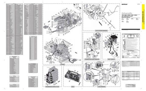
12K, 120K, 120K2, 140K, 140K2, and 160K Motor Grader Electrical System
51
150
94
80 CONN 46
119 CONN 45 92
81 74
Data valid but above normal operational range.
1
Data valid but below normal operational range.
2
Data erratic, intermittent, or incorrect.
3
Voltage above normal or shorted high.
4
Voltage below normal or shorted low.
5
Current below normal or open circuit.
6
Current above normal or grounded circuit.
7
Mechanical system not responding properly.
8
Abnormal frequency, pulse width, or period.
78
CONN 23
Abnormal update. Abnormal rate of change.
11
Failure mode not identifiable.
12
Bad device or component.
13
Out of calibration.
14
Parameter failures.
15
Parameter failures.
16
Parameter not available.
17
Module not responding.
18
Sensor supply fault.
19
Condition not met.
20
Parameter failures.
83
85
CONN 6
88
35 118 68
A
22 31
© 2012 Caterpillar, All Rights Reserved
E172
High Air Filter Restriction
E194
High Exhaust Temperature
E198
Low Fuel Pressure
E265
User Defined Shutdown
E360
Low Engine Oil Pressure
E361
CAB PLATFORM HARNESSES
CONN 28
5 95
CONN 29 10 CONN 30
90
34 69
CONN 16
146
110
18
T
Pressure Symbol
44
CONN 26
FRONT VIEW OF GUAGE CONSOLE
16 38
106 40
66
143
135
128
133
CONN 54 CONN 55 CONN 49
120
41 97
Switch (Normally Closed): A switch that will open at a specified point (temp, press, etc.). No circle indicates that the wire cannot be disconnected from the component.
113
Ground (Wired): This indicates that the component is connected to a grounded wire. The grounded wire is fastened to the machine.
148
109 4
Switch (Normally Open): A switch that will close at a specified point (temp, press, etc.). The circle indicates that the component has screw terminals and a wire can be disconnected from it.
42
149
Reed Switch: A switch whose contacts are controlled by a magnet. A magnet closes the contacts of a normally open reed switch; it opens the contacts of a normally closed reed switch.
15
108
23
Component Identifiers (CID¹) Module Identifier (MID²) Transmission Control (MID No. 081)
43
116
17
117 37 45
Programmable Parameter
High Engine Coolant Temperature
0444
Magnetic Switch (Start Relay)
E362
Engine Overspeed
0520
Configuration (Transmission)
E390
Fuel Filter Restriction
0585
Speed Sensor (Transmission Output) (No. 1)
E441
Idle Elevated to Increase Battery Voltage
0637
Backup Alarm
E539
High Intake Manifold Air Temperature
0668
Transmission Control (Shift Lever)
0669
Speed Sensor (Transmission Input)
0673
Speed Sensor (Transmission Output) (No. 2)
0868
Indicator Lamp (Automatic shift)
1401
Solenoid Valve (Forward High)
1402
Solenoid Valve (Forward Low)
1403
Solenoid Valve (Reverse)
1404
Solenoid Valve (Speed Clutch) (No. 2)
1405
Solenoid Valve (Speed Clutch) (No. 3)
1406
Solenoid Valve (Speed Clutch) (No. 1)
1407
Solenoid Valve (Low Range)
E627
Parking Brake Applied with Machine In Motion
1408
Solenoid Valve (High Range)
E762
Machine Driven with Cold Transmission
1484
Limit Switch (Inching Pedal)
Clock Manual Alignment Required
Sender: A component that is used with a temperature or pressure gauge. The sender measures the temperature or pressure. Its resistance changes to give an indication to the gauge of the temperature or pressure.
T
CONN 12
129
Relay (Magnetic Switch): A relay is an electrical component that is activated by electricity. It has a coil that makes an electromagnet when current flows through it. The electromagnet can open or close the switch part of the relay.
131
Solenoid: A solenoid is an electrical component that is activated by electricity. It has a coil that makes an electromagnet when current flows through it. The electromagnet can open or close a valve or move a piece of metal that can do work.
64 63
91
114
Magnetic Latch Solenoid: A magnetic latch solenoid is an electrical component that is activated by electricity and held latched by a permanent magnet. It has two coils (latch and unlatch) that make electromagnet when current flows through them. It also has an internal switch that places the latch coil circuit open at the time the coil latches.
CONN 11 2
CONN 20
Harness and Wire Symbols
CONN 19
46 87
Wire, Cable, or Harness Assembly Identification: Includes Harness Identification Letters and Harness Connector Serialization Codes (see sample).
67
CONN 40 86
Harness Identification Letter(s): (A, B, C, ..., AA, AB, AC, ...)
L-C12 3E-5179
AG-C4 111-7898
61
L-C12 3E-5179
Harness Connector Serialization Code: The "C" stands for "Connector" and the number indicates which connector in the harness (C1, C2, C3, ...).
1
Part Number: for Connector Plug
Part Number: for Connector Receptacle
2 Plug
CONN 14 107 CONN 4 6
9
UNSWITCHED POWER FUSE BLOCK
7
CONN 2 CONN 1
CONN 3
SWITCHED POWER FUSE BLOCK
Receptacle Pin or Socket Number
1 2
Deutsch connector: Typical representation of a Deutsch connector. The plug contains all sockets and the receptacle contains all pins.
1 2
Sure-Seal connector: Typical representation of a Sure-Seal connector. The plug and receptacle contain both pins and sockets.
5A
1580
Component Part Number
9X-1123
Fuse (5 Amps)
325-AG135 PK-14 Harness identification code: This example indicates wire group 325, wire 135 in harness "AG".
Wire Gauge Wire Color
57
SHIFT CONSOLE
STEERING AND GUAGE CONSOLES 8 CONN 24
Off-Machine Switch Specification
28 REAR VIEW OF RELAY PANEL
33
29
Part No.
14
72
Function
114-5333
A/C High Pressure
114-9281
Brake System Pressure LH/RH
149-6371
A/C Low Pressure
275-1253
Fuel Pressure
297-1140
Park Brake Pressure
CONN 39
24
141
56 CONN 38
CHASSIS
OVERHEAD FUSE BLOCK
Actuate
Deactuate
275 to 1750 kPa¹
-
(39.9 to 253.8 psi)
-
Contact Position Normally Open²
640 kPa MAX
530 ± 40 kPa
(92.8 psi MAX)
(76.9 ± 5.8 psi)
103.4 ± 13.8 kPa
34.5 ± 7 kPa
(15 ± 2 psi)
(5 ± 1 psi)
110.3 ± 13.8 kPa
69 kPa MIN
(16 ± 2psi)
(10 psi MIN)
640 kPa MAX
530 ± 40 kPa
(92.8 psi MAX)
(76.9 ± 5.8 psi)
Normally Open Normally Open Normally Closed Normally Closed
¹ With increasing pressure the closed condition can be maintained up to 2800 kPa (405 psi), with decreasing pressure the closed condition can be maintained down to 170 kPa (25 psi).
CONN 37
² Contact position at the contacts of the harness connector.
CONN 36
CONN 10
144
21
130
136
121
54
CONN 52
49
Resistor, Sender and Solenoid Specifications Part No.
Component Description
7T-4003
Resistor
9G-1950
Resistor
134-2540
Resistor
7W-9943
Sender
332-7657
122
Indicator Lamp (Transmission Filter Bypass )
Sender
Resistance (Ohms)¹
Front Defrost
10 ± 5%
HVAC 2
Overall: 2 ± 5%
HVAC 1
Each Side of Tap: 1 ± 5%
CAN 1/2
120 ± 10%
Coolant Temperature
50 Empty: 240-250
Fuel Level
Full: 28-33
Transmission 1 (Forward High)
145-1144
Solenoid
152-8346
Solenoid
Centershift Pin
32.6 ± 1.6
163-0872
Solenoid
A/C Clutch
17.6 ± 0.6
185-0008
Solenoid
Park Brake
8.7 ± 0.4
71.9 ± 2
Transmission 3 (Reverse)
Transmission 2 (Forward Low) Transmission 4 (2nd)
103 123
Component
0268
E861
Ground (Case): This indicates that the component does not have a wire connected to ground. It is grounded by being fastened to the machine.
CONN 31
101
Temperature Sensor (Transmission Oil)
Coasting in Neutral Warning
Circuit Breaker Symbol
Flow Symbol
Fuse: A component in an electrical circuit that will open the circuit if too much current flows through it.
39
CONN 18
Level Symbol
Symbols and Definitions
CONN 51
Electrical System Voltage
E049
Temperature Symbol
CONN 25
124
0177
Condition
Symbols
112
71
0168
Event Code
Harness And Wire Electrical Schematic Symbols
145
77
125
CID
Event Codes Transmission Control
Printed in U.S.A.
¹The FMI is a diagnostic code that indicates what type of failure has occurred.
Condition High Fuel Pressure
160K: SZM1-UP JBP1-UP
CONN 35
9 10
Event Codes Engine Control E096
140K2: SZW1-UP
140K: JPA1-UP SZL1-UP
120K2: SZS1-UP
93
CONN 5
138
Event Code
120K: SZN1-UP JAP1-UP
30
Failure Description
0
12K: JJA1-UP SZP1-UP
115
127
11
Failure Mode Identifiers (FMI)¹ FMI No.
0262
A
1
89
65
Engine Timing Calibration
12 134
59 CONN 7
CONN 43
52
13
27
CONN 22
CONN 8
The connectors shown in this chart are for harness to harness connectors. Connectors that join a harness to a component are generally located at or near the component. See the Component Location Chart.
0261
1627
55 CONN 21
CONN 44
50
Schematic Location
0002
0253
CONN 47
32
47
0001
Engine Speed Sensor
26
Connector Location
Component
0190
KENR8244-05 February 2012
3 19
73
Component Identifiers (CID¹) Module Identifier (MID²) Engine Control (MID No. 036) CID
60
186-1526
Solenoid
Transmission 5 (3rd)
31 ± 3
Transmission 6 (1st) Transmission 7 (Low Range) Transmission 8 (High Range)
239-1134
102
Solenoid
Start Aid
20
¹ At room temperature unless otherwise noted.
111
48 139
CONN 32
100 104
CONN 33
98 105
53
99
70 CONN 13
CONN 34
58
Related Electrical Service Manuals Title Alternator:
20
TRANSMISSION CONTROL VALVE
HVAC
CAB HARNESSES
Form Number 6N-9294 (35A STD)
SENR4978
197-8820 (95A ATCH)
SENR4130
Transmission Control:
KENR6680
Engine Control:
KENR5407
(Dimensions: 56 inches x 35 inches)
Wire Number
42 Page,
Wire Color
KENR8244-05
Wire Description Wire Number