1 minute read
PARKING THE MACHINE


QUICK IMPLEMENT INSTALLATION AND REMOVAL (optional)
Assembly
WARNING: Never put your hands inside the quick coupler if the engine is running.
STEP 1 STEP 4
1 2
1
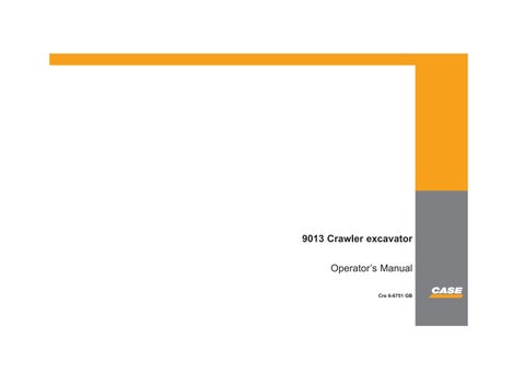
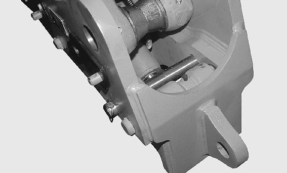
CK99G002 Install the quick coupler on the dipper and on the connecting rod using the CASE pins (1) supplied and connect the hydraulic connections.
STEP 2
Make sure that the tool to be installed is in a safe position on flat, level ground and is equipped with its CASE genuine pins.
STEP 3
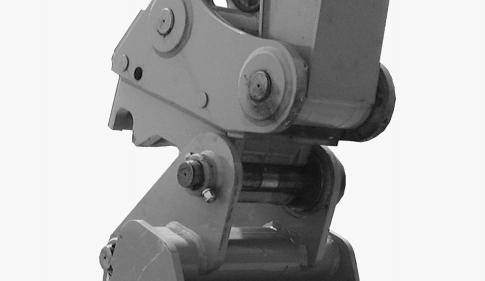
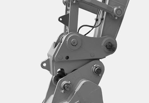
CK99H001 Operate the dipper control lever so as to bring the quick coupler hook (1) around the tool pin (2).
STEP 5
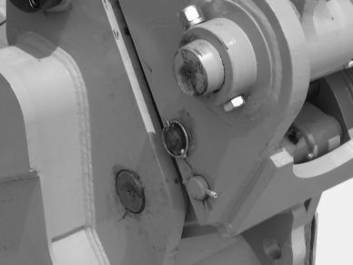
CK97A009 Remove the safety shaft and the locking pin.
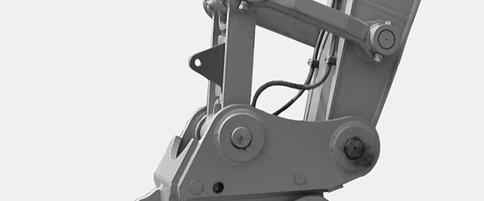
CK99G001 Place the switch in the unlocked position. See “Quick coupler locking and unlocking control switch” in the “Controls/Instruments/Accessories” Section.
107
TRIM THIS EDGE
RIGHT PAGE TRIM THIS EDGE
Template Name: OM_1_colTemplate Date: 1994_04_29
Template Date: 1994_04_29Template Name: OM_1_col
TRIM THIS EDGE
STEP 6
CK99H002 Operate the bucket control lever so that the pin is completely engaged in the quick coupler hook.
STEP 7 STEP 8
CK99G001 Place the switch in the locked position. See “Quick coupler locking and unlocking control switch” in the “Controls/Instruments/Accessories” Section.
IMPORTANT: Check that the quick coupler is correctly engaged on the tool pins.
STEP 9
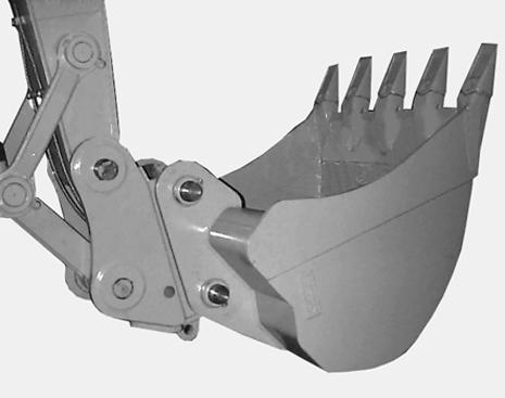
CS99G514 Raise the dipper and retract the bucket until the teeth are in the vertical position.
CK99H003 Install the safety shaft and locking pin. IMPORTANT: It is essential that the safety shaft and locking pin are in place.
108
TRIM THIS EDGE
LEFT PAGE