6 minute read
TRANSPORTING THE MACHINE


Template Date: 1994_04_29Template Name: OM_1_col
TRIM THIS EDGE
LOAD HANDLING LIMITS
CS98F554 The load handling chart shows the different authorized loads which can be lifted at different reach points, depending on the type of attachment installed on the machine.
The machine must be on flat, firm, level ground with the front axle locked. The stabilizers and the dozer blade (if equipped) must be resting on the ground. Loads are given in daN (1daN = 1.02 kg), for a machine without tool, with the bucket cylinder rod completely retracted, for full upperstructure swing, with a safety margin factor: - of 33% based on stability - of 15% based on hydraulic capacity with the end of the dipper as the load fixing point.
If the load fixing point is the connecting rod/bucket linkage pin or the eye located on the Quick Coupler (if equipped), the weight of the Quick Coupler (if equipped) (weight indicated on the manufacturer’s plate) and the weight of the bucket, if installed on the machine or on the Quick Coupler, must be subtracted from the values given in the chart. See “Buckets” in the “Specifications” Section. The reach is given from the machine’s swing axis and the height is taken from the load fixing point. NOTE: The loads given are valid for the full working range height at the reach point indicated.
122
TRIM THIS EDGE
LEFT PAGE
OVERLOAD INDICATOR (optional)
WARNING: The indicator must be adjusted each time the attachment is changed, in accordance with the load handling chart.
STEP 1
Park the machine on flat, firm, level ground and then lower the stabilizers and the dozer blade (if equipped) to the ground.
STEP 2 STEP 4
Move the load to the position specified in the load handling chart for the attachment installed on the machine.
STEP 5
PH07533 Place the front axle locking/unlocking switches in the manual locked position.

WARNING: The front axle must be locked when handling a load.
STEP 3

Attach a load to the load handling point or to the Quick Coupler eye (if equipped). The weight of the load must correspond to the value given for the “maximum reach” point in the load handling chart. See “Load handling”.
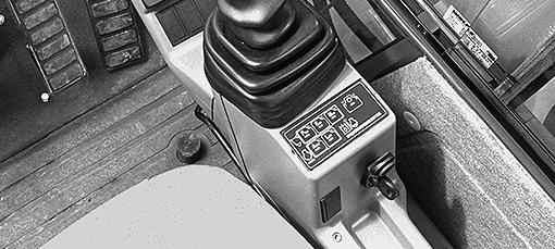
PH07521 Tilt the overload indicator switch forward.
STEP 6
1
2
CD96M088 Unscrew the locknut (1) on the indicator which is located in front of the boom cylinders. Then using the screw (2), find the point at which the indicator lamp on the instrument panel comes on.
123
TRIM THIS EDGE
RIGHT PAGE TRIM THIS EDGE
Template Name: OM_1_colTemplate Date: 1994_04_29
Template Date: 1994_04_29Template Name: OM_1_col

TRIM THIS EDGE
STEP 7
1
Retighten the locknut (1).
CD96M088
TRANSPORTING THE MACHINE On a railway wagon
Since transport by rail is subject to special regulations, consult an approved organization.
On a trailer
WARNING: The machine can slip and fall from a trailer or ramp and cause serious injury. Make sure the trailer and ramps are clean. The machine must be aligned with the trailer before loading.
You must know the safety rules and regulations before transporting this machine. Make sure both the trailer and the machine are equipped with the proper safety equipment.
Loading
STEP 1
Put a block behind the trailer wheels. Install the trailer side extensions (if equipped).
CD95M248
124
TRIM THIS EDGE
LEFT PAGE
STEP 2

CD98J005 Raise the stabilizers (if equipped) and the dozer blade (if equipped) completely.
STEP 3 STEP 4
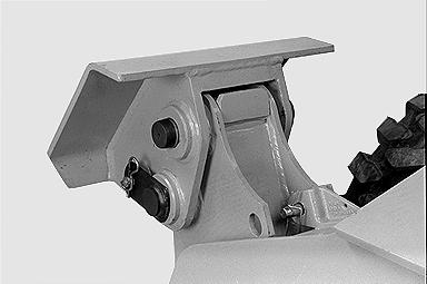
PG02003 Remove the lock pins and split pins from the stabilizer pads so that they are in the swivel position, then place the lock pins and split pins in the tool box.
STEP 5

PG02008 Lock the stabilizers, using the lock pins and split pins.
CD95N039 Install the registration plate assembly (specific to certain countries). TRIM THIS EDGE
125
TRIM THIS EDGE
RIGHT PAGE
Template Name: OM_1_colTemplate Date: 1994_04_29
Template Date: 1994_04_29Template Name: OM_1_col

TRIM THIS EDGE
STEP 6 (Machine with attachment) STEP 7

PDH0088 Align the machine with the trailer, with the rear wheels towards the ramps. Raise the attachment and bring it to about 20cm above the trailer bed.
IMPORTANT: In this position, the travel controls and the steering are inverted.
STEP 6 (Machine without attachment)
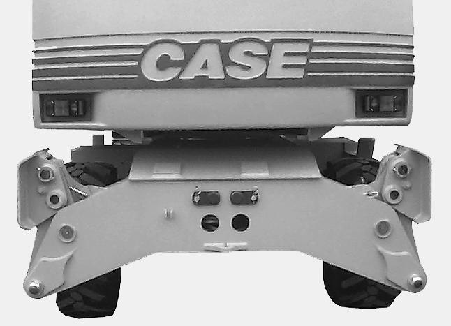
PH07533 Place the front axle locking/unlocking switches in the unlocked position (indicator lamp on instrument panel comes on).
WARNING: The front axle must be unlocked when loading the machine.
STEP 8
PDH1142 Align the machine with the trailer, with the rear wheels towards the ramps. Swing the upperstructure so that the operator’s compartment is over the front wheels.
PH07517
(Machine with attachment)
Press down the travel pedal and use the travel control lever to adjust the travel speed. Move the machine slowly forward (job site speed) onto the ramps, keeping the attachment about twenty centimeters above the trailer bed.
126
TRIM THIS EDGE
LEFT PAGE
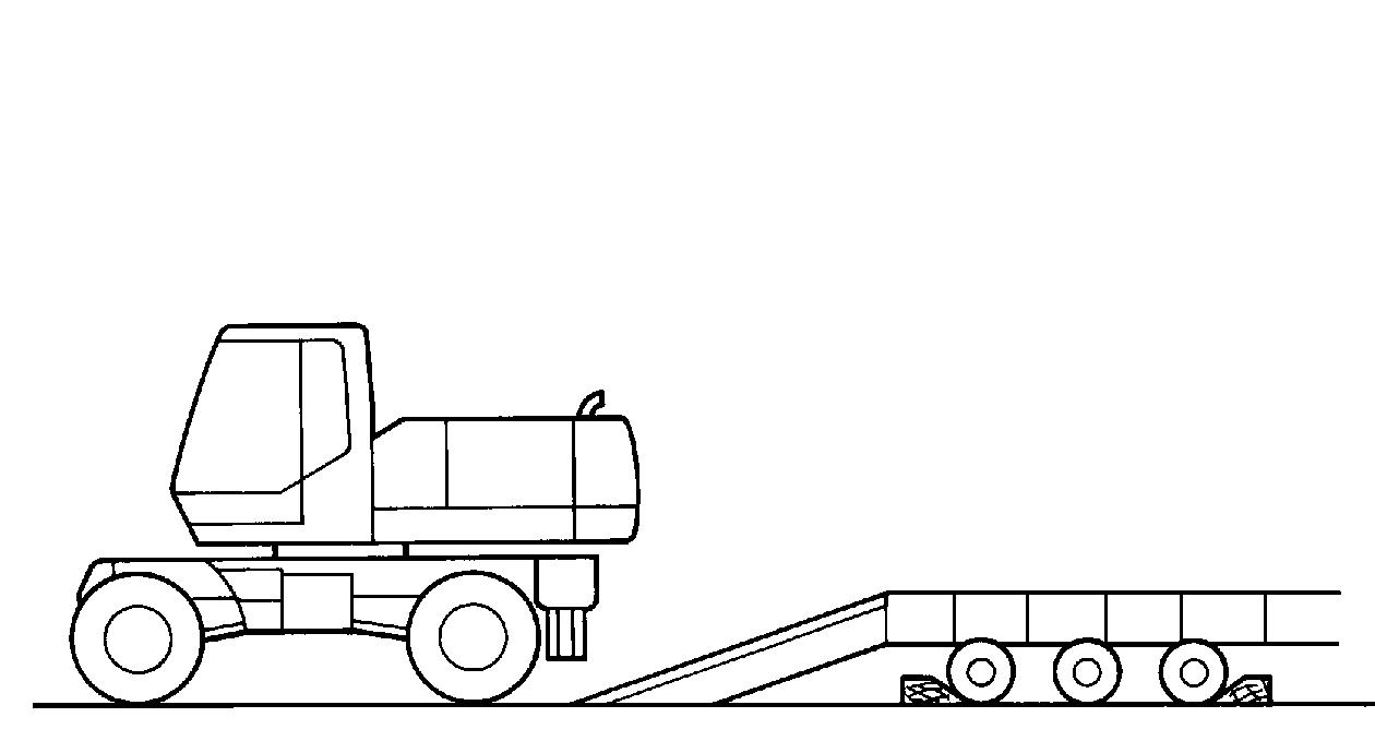
(Machine without attachment)
Press down the travel pedal and use the travel control lever to adjust the travel speed. Move the machine slowly backward (job site speed) onto the ramps. IMPORTANT: For machines without attachment, it is very important to drive the machine onto the trailer in reverse, otherwise the machine can overturn.
STEP 9 (Machine with attachment)

PDH0089 When the machine is completely loaded onto the trailer, raise the attachment slightly and swing the upperstructure so as to bring the attachment around towards the ramps.
STEP 10 (Machine with attachment)


PDH0090 Position the machine completely to the front of the trailer and lower the attachment onto the trailer bed.
STEP 10 (Machine without attachment)
PDH1143 Position the machine completely to the front of the trailer.
STEP 11
Place the travel control lever in the neutral position and engage the upperstructure locking lever. Immobilize the machine using the parking/work brake control switch. TRIM THIS EDGE
127
TRIM THIS EDGE
RIGHT PAGE