2 minute read
TOWING THE MACHINE


Template Date: 1994_04_29Template Name: OM_1_col


TRIM THIS EDGE
STEP 2
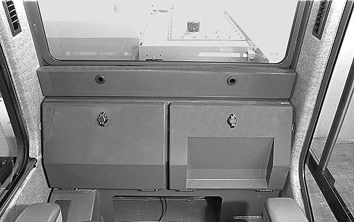
Raise the cab carefully and position it correctly on the cab floor. IMPORTANT: Make sure that the seal located at the back of the cab is correctly in place.
STEP 3 STEP 4
PH07911 PH07911 Reconnect the electrical power point to its base after removing the protective cap. Reconnect the windshield washer hose. Reconnect the radio aerial (if equipped).
STEP 5
PH00305 Install and tighten the four cab mounting screws to a torque of 120 Nm and reposition the floor cover correctly at the front of the operator’s compartment. Install the trim.
PH07909
134
TRIM THIS EDGE
LEFT PAGE
STEP 6
PH07824 Remove the lifting equipment and install the two plastic plugs on the cab roof.

135
TRIM THIS EDGE
RIGHT PAGE TRIM THIS EDGE
Template Name: OM_1_colTemplate Date: 1994_04_29
Template Date: 1994_04_29Template Name: OM_1_col
TRIM THIS EDGE
WARNING: Towing is a delicate operation. There is always a certain amount of risk for the operator. The manufacturer’s guarantee does not apply to accidents or problems which occur while towing.
WARNING: Never use the towing eye to tow another vehicle.
WARNING: The machine must be towed very slowly, for a short distance and only if absolutely necessary.
WARNING: A towing bar must be used for all towing operations.
IMPORTANT: Before towing, you must install the stabilizer (if equipped) and dozer blade (if equipped) lock pins. See “Road travel” in the “Job Site and Road Operation” Section.
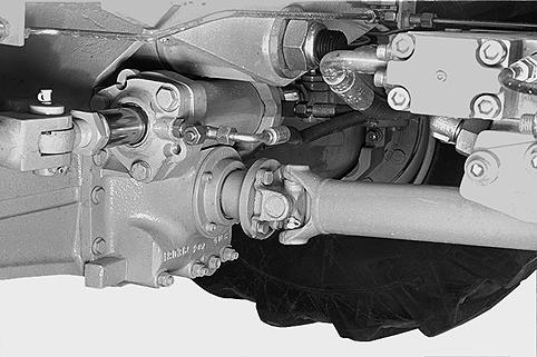
For all towing operations, the front and rear axle universal joints must be uncoupled.
STEP 1
Place blocks under the machine wheels.
Removal of universal joints
Tools required
-One 19 mm wrench for hexagonal head screws -One towing bar
STEP 2
Mark both parts before uncoupling them. NOTE: Marking the parts will facilitate their reassembly.
STEP 3
Support the front axle universal joint using a sling attached to the undercarriage.
STEP 4
PH07813 Remove the four screws from the front axle universal joint.
STEP 5
Repeat Steps 2 through 4 for the rear axle universal joint.
136
TRIM THIS EDGE
LEFT PAGE