7 minute read
Every 500 hours work


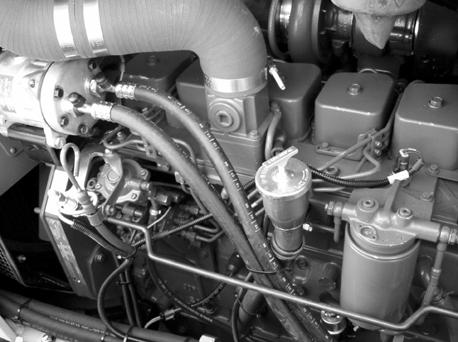
Replacing the transmission/converter delivery filter
1.Clean the support base and the surrounding area. 2.Loosen filter F2 and replace it with a new one.
Before installing the new filter, lubricate the gasket with engine oil, then screw it on the support. 3.After the gasket touches the base, tighten the filter 3/4 turn further. The tightening must be done exclusively by hand.
F2
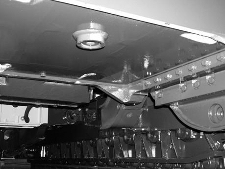
1850-2M0129
F2. Transmission/torque converter oil filter (delivery)
Oil refilling
Retighten plug Ton the machine, after cleaning it and fill with oil through filler neck B up to the level on the upper mark, etched on the oil dipstick. Start the engine and run it for a few minutes. Shut-off the engine and after a few minutes, top-off the oil in the circuit, always checking as described at point (2) of the MAINTENANCE TABLE.
WARNING Do not run the engine of this machine in closed areas without proper ventilation to remove deadly exhaust gases.
Make sure exposed personnel in the area of operation are clear of the machine before moving it or its attachments. WALK COMPLETELY AROUND the machine before mounting. Sound horn.
WARNING Avoid environment pollution. The used fluids, such as hydraulic oil, lubricants, coolants and the filter elements soaked with these fluids, must be eliminated according to local or national current regulations qualifying these materials as polluting, harmful and dangerous waste.
D150-2M109
18.ENGINE SUMP - Change oil (The oil change is performed at the same time of the replacement of the filter)
Note – Comply strictly with the oil change interval at 500 hours or 6 months. The oil change and the replacement of the filter have the purpose of eliminating contaminants suspended in the oil.
Note – If the fuel used has a sulphur content higher than 1 %, the engine oil change must be done every 150 hours.
Note – Drain the oil when it is hot and the contaminants are in suspension, thus proceed as follows:
3.To facilitate the draining, open the left front panel of the engine compartment indicated and loosen the oil filler neck cap B.
For the draining, use a container with a capacity of at least 20 lit (5 1/4 US Gal).
A B
D150-2M165
D150-2M097
1.Operate the engine until the coolant temperature reaches 60 °C (140 °F), then shut-off the engine. 2.Remove drain plug T located on the bottom of the machine using a 10 mm (0.39 in) Allen wrench.
MIN. MAX A
A. Engine oil dipstick B. Engine oil filler neck
D150-2M082
WARNING Use approved disposal sites or used oil collection centers. In case of doubts about the procedures for the management and disposal of used lube oils, contact the appropriate local authorities responsible for environmental protection.
T
T. Engine oil draining plug
1850-2M0119
WARNING Avoid prolonged and repeated contacts of the skin with used engine lube oil which could be dangerous to your health. Avoid prolonged and repeated contacts of the skin with used engine lube oil which could be dangerous to your health. -Avoid contact with skin or eyes. If contact occurs, immediately clean the area throughly. -Keep oil and fluids away from children.
WARNING Avoid environment pollution. The used fluids, such as hydraulic oil, lubricants, coolants and the filter elements soaked with these fluids, must be eliminated according to local or national current regulations qualifying these materials as polluting, harmful and dangerous waste.
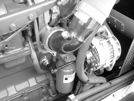
19.ENGINE OIL FILTER
Replacing the filter cartridge
When the oil stops flowing, refill with oil of a prescribed type and grade (see "FLUID CAPACITIES TABLE").
4.retighten draining plug T and refill with new oil through filler neck B, up to the maximum level marked on dipstick A. 5.run the engine at low idle; 6.shut-off the engine and, after a few minutes, topoff, if required.
Oil sump Total system capacity capacity
14.2 lit (3 3/4 US Gal) 16.3 lit (4 1/3 US Gal)
Open the upper and lower panels of the right engine compartment. The replacement of the filter must be done at the prescribed interval. Replace the filter, proceeding as follows: 1.clean the filter contact area and loosen it with a 90 - 95 mm (3.54-3.74 in) filter wrench; Note – It is possible the O-Ring may sticks to the filter head, thus, prior to installing a new filter, make sure that it has been removed.
2.fill the new filter with clean oil and lubricate the seal; 3.tighten the filter by hand. After the gasket touches its seat on the engine cylinder block, tighten 3/4 turn further.
D150-2M100
WARNING An excessive mechanical tightening can damage the threads and the gasket of the filter element.
WARNING Avoid environment pollution. The used fluids, such as hydraulic oil, lubricants, coolants and the filter elements soaked with these fluids, must be eliminated according to local or national current regulations qualifying these materials as polluting, harmful and dangerous waste.
D150-2M166
20.CAB VENTILATION AIR FILTER AND AIR
RE-CIRCULATION FILTER -
Replace
To reach the air cleaner, open the panel under the cab, on the left side of the machine. Remove the retaining device and extract the filter E using the appropriate handles.
Note – Before re-installing the filter, clean the inside of the air box.
E WARNING Wear safety glasses with side shields when using compressed air to clean parts, so that the danger of personal injuries due to flying particles is reduced. Limit the pressure to 2 bar (29 p.s.i.) in accordance with local and national regulations.
21.DOORS GREASE FITTINGS - Grease pivot
1650-2M040
RECIRCULATION AIR FILTER
Change the filter (F) located behind operator’s seat: -Unscrew the two retaining knobs (1) of the filter container. -Install a new filter into the container and tighten the two knobs. Lubricate the door hinges through the grease fittings indicated.
1
1
2 F
D150-2M111 1850-2M0102
Every 1000 hours work
22.ENGINE VALVES -
Valve clearance check (cold engine)
Have the valve clearance checked by specialized personnel. The valve clearance adjustment must be performed with cold engine or, in any case, at a temperature lower than 60 °C (140 °F).
Valve clearance -Intake ...................................0.25 mm (0.0197 in) -Exhaust ................................0.50 mm (0.0098 in)
A
B
C
D150-2M112
A. Feeler gauge - B. Clearance adjustment screw C. Wrench 14 mm (0.55 in).
Lock the nut to a torque of 24 Nm (17.70 ft lbs) and recheck the valve clearance.
23.BEVEL GEAR - STEERING AND BRAKES -
Change oil and wash suction filter
Oil draining
Place a container with at least 65-70 lit (17 - 18 1/2 US Gal) capacity under the transmission housing. Remove plug A and let the oil drain completely. Retighten the plug after cleaning them properly.
Cleaning the suction filter and magnetic rod
Tilt the cab and loosen nut 1 to remove mesh filter 4 and magnetic rod 5. Wash both of them with solvent. Clean the container inside.
WARNING Do not use gasoline or any flammable fluid to clean parts. Use approved, non flammable, non toxic commercial solvents only. Wear safety glasses with side shields when using compressed air to clean parts, so as to reduce the danger of personal injuries caused by flying particles. Limit the pressure to 2 bar (29 p.s.i.), in accordance with local or national regulations.
1 2
3 4
5
F
Reinstall the filter, the magnetic rod and the cover. Check and top-off the oil level after changing it.
1850-2M0134
F. Transmission/torque converter suction filter - 1. Nut 2. Cover - 3. Gasket - 4. Mesh filter - 5. Magnetic rod.
B
A. Steering and brakes oil draining plug
D150-2M185
Oil filling
Refill with oil up to the prescribed level, indicated by the mark etched on dipstick A. Start the engine and let it run at about 1000 rpm. Actuate the steering a few times. Stop the engine and after a few minutes check that the oil level reaches the upper mark on the dipstick. Top-off, as required, through the plug hole.
Dipstick A
D150-2M109
The correct oil level must be between the two marks. Reinstall the filter , magnetic rod and the cover. Check and top-off the oil level after changing it.
WARNING Do not run the engine in closed areas without proper ventilation to remove deadly exhaust fumes.
WARNING Avoid environment pollution. The used fluids, such as hydraulic oil, lubricants, coolants and the filter elements soaked with these fluids, must be eliminated according to local or national current regulations qualifying these materials as polluting, harmful and dangerous waste. 24.TORQUE CONVERTER/TRANSMISSION
HYDRAULIC CIRCUIT -
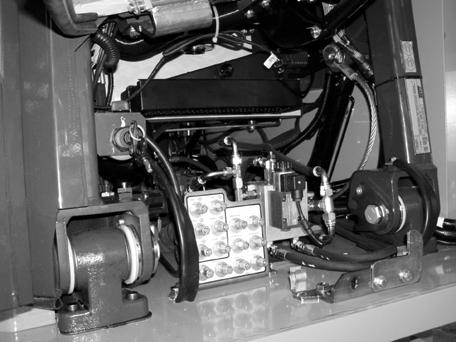
Clean filter and magnetic rod
Tilt the cab, loosen nut 1 and remove mesh filter 4 and magnetic rod 5. Wash both of them with solvent. Clean the container inside.
WARNING Do not use gasoline or any flammable fluid to clean parts. Use approved, non flammable, non toxic commercial solvents only. Wear safety glasses with side shields when using compressed air to clean parts, so as to reduce the danger of personal injuries caused by flying particles. Limit the pressure to 2 bar (29 p.s.i.), in accordance with local or national regulations.
1 2
3 4 5
F
1850-2M0136
F. Transmission/torque converter suction filter - 1. Nut 2. Cover - 3. Gasket - 4. Mesh filter - 5. Magnetic rod