2 minute read
Every 100 hours work


10.BLADE CYLINDER LINKAGE PIVOTS -
Grease pivots
Pump grease into the lube fittings of the blade cylinder support.
WARNING Stop the machine in accordance with the procedures prescribed in the Operation and Maintenance Manual, prior to lubricating or performing any intervention. Always lower the equipment to the ground prior to performing any type of maintenance operation. 11.RIPPER LINKAGE PIVOTS -
Grease pivots
Pump grease into the fittings of the ripper linkage. The black arrows indicate that the same fittings are located on the opposite side as well.
D150-2M096
1650-2M038
Every 250 hours work
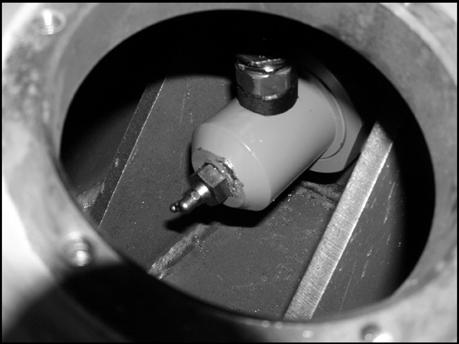
12.TRACK CHAINS - Checking the sag
WARNING Fluid under pressure; to release the tension of the track chain, follow the procedures in the "Operation and Maintenance Manual".
C
If the sagging of the track chains in section Cincluded between the support roller and the idler exceeds 30 - 40 mm (1 3/16 - 1 5/8 in).
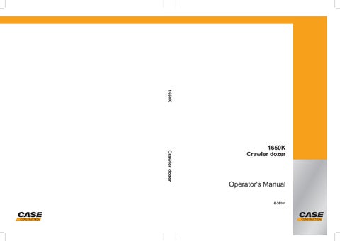
3÷4 cm MAX. DANGER Fluid under pressure. Do not reduce the tension of the track chain by loosening pressure relief valve VS. Do not remove the grease fitting installed on adjusting valve VR.
13.BRAKE SYSTEM -
Operating check
Pump grease into grease fitting I indicated of valve VR of the adjustment cylinder, until the normal tension of the track chain is obtained.
To increase sag, discharge grease from the cylinder, loosening slightly adjustment valve VR and backing the machine up a few yards, if necessary.
Retighten valve VR.
VS
D150-2M101
Remove the cover indicated by removing the six securing screws.
D180DIA019
I VR
D180DIA020
I. Grease fitting; VR. Track chain tension adjustment valve; VS. Pressure relief valve.
Note – The track chain tension must be somewhat lesser in muddy, very wet terrains and when sand, gravel, snow and ice are present.
Check the correct operation of the brake system doing a series of tests with machine at maximum speed descending a slope. When the brake pedal is depressed, the machine must come to a stop after a braking distance that should be sufficiently short and so as to ensure an adequate operational safety.
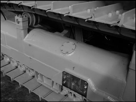
14.MESH FUEL FILTER - replacement
WARNING Do not use gasoline nor any flammable fluid to clean parts. Use approved, non flammable, non toxic commercial solvents only.
1.Remove the rear panel under the fuel reservoir and close valve S shutting-off the fuel.
WARNING Avoid environment pollution. The used fluids, such as hydraulic oil, lubricants, coolants and the filter elements soaked with these fluids, must be eliminated according to local or national current regulations qualifying these materials as polluting, harmful and dangerous waste.
S
D150-2M104
2.Open the engine compartment upper and lower panels on the left side of the machine.
3.Replace mesh fuel filter A loosening screw C and disconnecting the two collars B. Make sure that no open flames or sparks are present in the vicinity.
After replaced the filter, re-open valve S and actuate priming pump P e few times.
B
A C
B P
D150-2M167