2 minute read
Tram primary planetary gear........................................5


BI016912-04 (EN-US)
Advertisement
primary planetary gear removal Tram primary planetary gear removal and installation
To remove the primary planetary gear:
1. Lower the conveyor tail section until it is level with the floor.
2. Lower the gathering head and cutter head assemblies until they touch the floor.
3. Disconnect the trailing cable to de-energize the miner. Follow all Federal and mine regulations for lockout/tagout.
WARNING! Follow all federal and mine lockout/tagout regulations. Failure to do so could result in machine damage or serious injury or death to personnel.
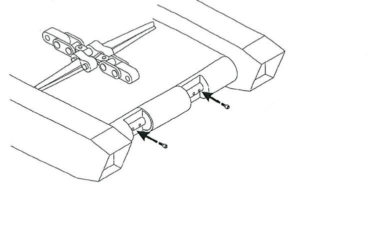
4. Remove the two rub rail pins that secure the tram rub rail to the two rub rail sections adjacent to it and remove the tram rub rail to expose the tram gear case.
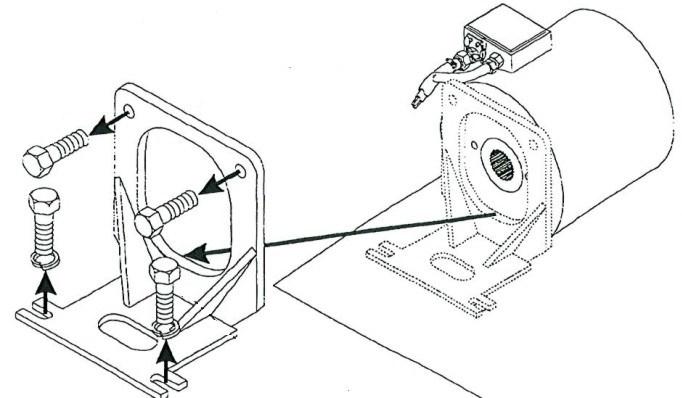
5. Remove the tram motor (see Tram motor removal and installation procedure in this chapter).
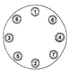
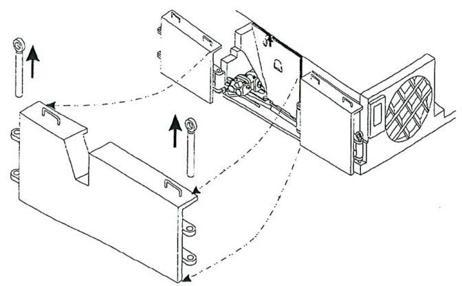
6. Remove the socket head capscrews that secure the motor adapter plate to the primary gear ring (and also secure the primary planetary carrier assembly to the tram case) (Fig. 189).
7. Remove the motor adapter plate from the tram case.
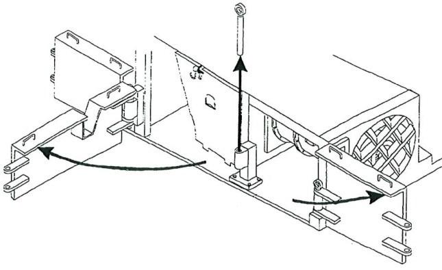
8. Carefully slide the primary planetary carrier assembly out of the primary gear ring and remove the assembly from the tram case.
9. Carefully slide the primary gear ring out of the tram case.
Fig. 189: Tram primary gear removal
Tram case
Motor adapter plate
Socket head capscrews
Primary planetary gear ring
Primary planetary carrier assembly
primary planetary gear installation
To install the tram primary planetary gear:
1. Insert alignment dowels into four of the sixteen capscrew holes in the tram case (Fig. 190).
2. To facilitate gear ring insertion, mark the mounting holes of the primary planetary gear ring that corresponds to the holes in which dowels were placed.
3. Slide the primary planetary gear ring onto the alignment dowels so the dowels appear through the marked holes.
Fig. 190: Alignment dowels and gear ring mounting
Alignment dowels
Primary planetary gear ring Tram case
Tram drive pinion gear

Mounting marks (match with alignment dowels)
4. Carefully insert the primary planetary gear assembly into the gear ring, ensuring that the extension of the sun gear faces out from the centerline of the miner and that the internal gear teeth of the primary carrier are seated securely onto the tram drive pinion gear.
5. Place the two adapter plate dowels into two 1” holes on the bottom left and right corners of the adapter plate.
6. Orient the adapter plate with the adapter dowels along the bottom edge.
7. Slide the adapter plate onto the four alignment dowels.
8. Insert and tighten twelve socket head capscrews into the holes in the adapter plate not blocked by the alignment dowels.
9. Remove the four alignment dowels and insert and tighten the final four socket head capscrews to secure the adapter plate and gear ring to the tram case.
BI016912-04 (EN-US)
10. Torque the sixteen socket head capscrews to the appropriate amount (see Torque tables in Chapter 6 of this manual).
11. Install the tram motor in the tram case (see Tram motor removal and installation procedure in this chapter).
12. Replace the tram rub rail between the two adjacent rub rails and secure it with the two rub rail pins.
13. Refill the tram gear case with oil.