3 minute read
Hydraulic pump motor..................................................5

Hydraulic pump motor removal
1. Lower the conveyor tail section it is level with the floor.
2. Lower the gathering head and cutter head until they touch the floor.
3. Disconnect the trailing cable to de-energize the miner. Follow all Federal and mine regulations for lockout/tagout.
WARNING! Follow all federal and mine lockout/tagout regulations. Failure to do so could result in machine damage or serious injury or death to personnel.
4. Remove the hydraulic pump (see Hydraulic pump removal procedure in this chapter).
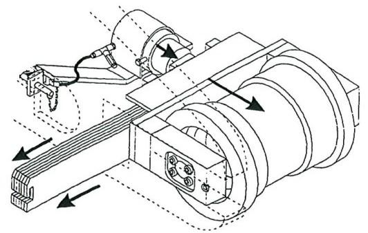
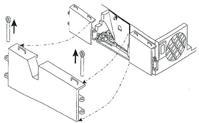
5. Remove the two hex head capscrews that secures the motor to the pump stand (Fig. 223).
6. Remove the two hex head capscrews and lockwashers that secure the pump stand to the tractor frame and remove the pump stand.
Fig. 223: Hydraulic pump stand removal
Hex head capscrew (2)
Pump stand
Hex head capscrew (2) Motor
BI016912-04 (EN-US)
7. Tag, disconnect, and cap the two cooling water hoses from the cooling water fittings on the pump motor.
8. Remove the cooling water fittings from the top left and right surface of the pump motor and store in a safe place.
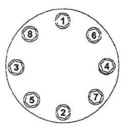
9. Remove the cover and its o-ring from the motor’s junction box by removing four hex head capscrews and lockwashers.
10. Locate the three taped power connections inside the junction box.
11. Strip off the three layers of tape covering each of the three lug connections inside the junction box.
12. Tag the three lugs to facilitate reconnection during motor installation.
13. Remove the hex head capscrew, flat washer, lockwasher, and hex head nut that secures the three power cable lugs to the three motor lugs.
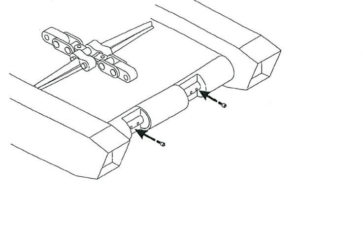
14. Remove the two socket head capscrews and lockwashers that secure the stuffing box’s half-moon clamp to the junction box.
15. Remove the clamp and slide the stuffing box out of the junction box. The power cable should be completely disconnected from the motor.
16. To prevent damage to the power cable lugs and gland assembly, cover the power cable and secure it to the miner in a safe location.
17. To protect the motor’s electrical connections, replace the motor junction box cover and secure it using four hex head capscrews and lockwashers.
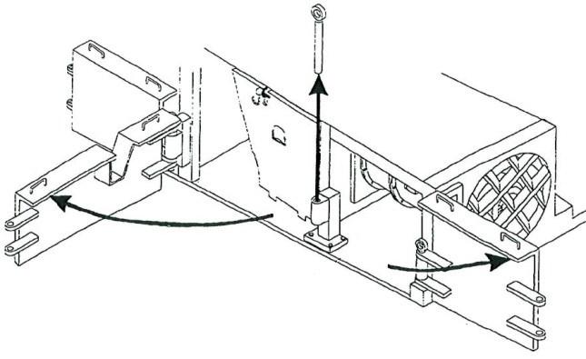
WARNING! The hydraulic pump motor is now detached from the tractor frame and can be removed. The hydraulic pump motor is extremely heavy. Prepare to support its weight before removing it from the tractor frame.
18. Carefully slide the hydraulic pump motor out of the tractor frame.
Hydraulic pump motor installation
1. Slide the hydraulic pump motor into position in the tractor frame.
2. Remove the four hex head capscrews and lockwashers that secure the junction box cover and remove the cover and its oring.
3. Insert the three lugs of the power cable (with gland and stuffing box already installed) into the motor’s junction box.
4. Replace the stuffing box’s half-moon clamp in its channel to secure the stuffing box in the junction box.
5. Tighten the two socket head capscrews to secure the clamp to the junction box.
6. Inside the junction box, locate the motor’s lug connections. Match the motor lug connections to the corresponding power cable lugs (refer to the wiring diagram supplied in your parts manual).
7. Attach the first motor lug to its corresponding power cable lug by inserting a hex head capscrew through the motor lug, through the power cable lug, through a flat washer, and through a lockwasher. Secure the capscrew with a hex nut. Repeat this step for the other two lugged connections.
8. When all three connections have been secured, wrap each of the three connections with a layer of rubber tape, then a layer of black tape and finally a layer of glass tape.
9. Replace the junction box O-ring and cover.
10. Insert the four hex head capscrews and lockwashers to secure the junction box cover and tighten.
11. Insert the two motor cooling water fittings into the pump motor cooling water ports.
12. Attach the two motor cooling water hoses to the fittings.
13. Position the pump stand against the motor and attach to the motor with two hex head capscrews.
14. Insert and tighten the two hex head capscrews and lockwashers to secure the pump stand to the tractor frame.
15. Install the hydraulic pump (see hydraulic pump installation procedure in this chapter).