1 minute read
Tail roller.......................................................................5


Tail roller removal
Advertisement
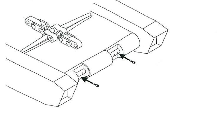
Reference Fig. 226:
1. Lower the gathering head and cutter head assemblies until they rest on the floor.
2. Slowly advance the conveyor chain until a connecting link moves onto the conveyor tail section slide pan.
3. Using the procedure outlined in Chain Tension, Loosen tension on the conveyor chain as much as possible (see Conveyor chain adjustment procedure I n this chapter).
4. Lower the conveyor tail section onto blocking so it is level with the floor.
WARNING! You could be seriously injured or killed by falling loads. Observe the safe working load limits of all blocking devices.
5. Disconnect the trailing cable to de-energize the miner. Follow all Federal and mine regulations for lockout/tagout.
WARNING! Follow all federal and mine lockout/tagout regulations. Failure to do so could result in machine damage or serious injury or death to personnel.
6. With conveyor chain tension removed, remove the retaining rings, or “T” pins, from the connecting link.
7. Remove the connecting link and its strap. The conveyor chain should now be separated. Move the two pieces of the conveyor chain out of the way to allow for easier removal of the conveyor tail roller assembly.
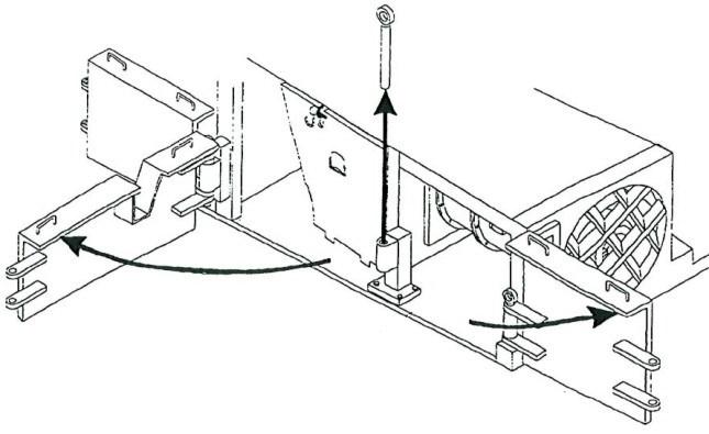
8. Remove the socket head capscrews that secure the tail roller assembly to the slide pan.
9. Remove the tail roller assembly from its location in the slide pan.
BI016912-04 (EN-US)
Fig. 226: Tail roller
Tail roller
Socket head capscrew
Tail roller installation
1. Insert the tail roller assembly into the proper location in the slide pan (Fig. 226).
2. Insert and tighten the socket head capscrews through the holes in the tail roller shaft and into the threaded holes in the slide pan (Fig. 226).
3. Reattach the two ends of the conveyor chain by replacing the connecting link.
4. Secure the connecting link by replacing the side strap and the retaining rings onto the ends of its pins.
5. Tighten the conveyor chain to the proper tension (see Conveyor chain adjustment procedure in this chapter).