6 minute read
Tram motor...................................................................5


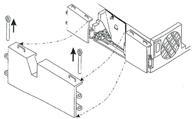
6. Remove the hex head capscrews and hi-collar lock washers that secure the input shaft access cover to the motor housing. Note that the cooling water hose support clamp is secured by one of the capscrews.
7. Remove the input shaft access cover and its o-ring.
Advertisement
8. Remove the retaining ring that secures the shaft plug in position.
9. Remove the shaft plug with o-ring that secures the input shaft in the motor (Fig. 187).
tram motor removal Tram motor removal and installation
To remove the tram motor:
1. Lower the conveyor tail section until it is level with the floor.
2. Lower the gathering head and cutter head assemblies until they touch the floor.
3. Disconnect the trailing cable to de-energize the miner. Follow all Federal and mine regulations for lockout/tagout.
WARNING! Follow all federal and mine lockout/tagout regulations. Failure to do so could result in machine damage or serious injury or death to personnel.
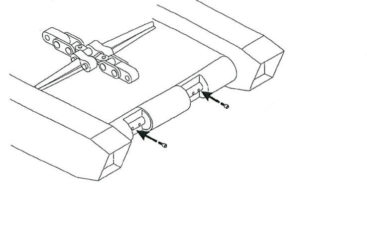
4. Remove the two rub ail pins that secure the tram rub rail to the two rub rail sections adjacent to it.
5. Remove the tram rub rail to expose the tram gear case and locate the tram drive motor inside the gear case (Fig. 186).
Fig. 186: Tram drive motor location
Tram drive motor
BI016912-04 (EN-US)
10. Pull the input shaft from the motor and store in a safe place.
11. Replace the input shaft access cover on the motor housing and secure the cover with the hex head capscrews and hi-collar lock washers.
12. Tag, disconnect, and cap the cooling water hoses or fittings from the cooling water fittings located on the top left and right corners of the tram motor.
13. Remove the cooling water fittings from the bottom left and right corners of the tram motor and store in a safe place.
14. Remove the hex head capscrews and disc lock washers that secure the tram motor bracket to the tram case.
15. Remove the socket head set screws that secure the tram motor bracket to the tram motor.
16. Remove the tram motor bracket from the tram motor.
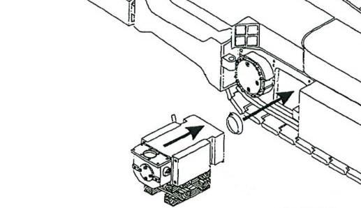
17. Carefully slide the tram motor out from the tram case until the motor’s electrical connection and hand hole cover are accessible.
18. Remove the socket head capscrews and hi-collar lockwashers that secure the hand hole cover to the motor housing.
19. Remove the hand hole cover and its o-ring from the motor housing.
20. Remove the socket head capscrews and lock washers that secure the stuffing box's half moon clamp to the junction box.
21. Remove the clamp and slide the stuffing box out of the junction box. The power cable should be completely disconnected from the motor.
tram motor installation WARNING! Do not reconnect the trailing cable to the miner while the power cable is detached from the motor. Serious injury or death or damage to the machine may result.
22. To prevent damage to the power cable lugs and gland assembly, cover the power cable and secure it to the miner in a safe location. The manufacturer also recommends replacing motor gear case input seals for all motors.
23. To protect the motor’s electrical connections, replace the motor hand hole cover and o-ring and secure using the socket head capscrews and hi-collar lock washers.
24. Carefully remove the tram motor from the tram case and slide onto blocking. Clean out tram motor housing.
25. Remove the tram motor cooling water bypass hose that connects the two cooling water fittings on the rear of the tram motor and store in a safe place.
26. Clean out tram motor housing.
WARNING! You could be seriously injured or killed by falling loads. Observe the safe working load limits of all blocking devices.
To install the tram motor:
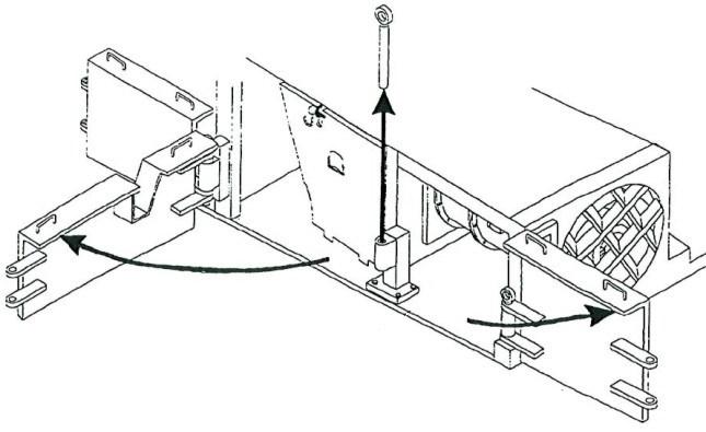
1. Replace the seal on the motor adapter plate, which is positioned against the primary planetary (Fig. 188).
2. Install fittings and install tram motor bypass hose on the rear of motor.
3. Slide the tram motor into the tram case, leaving the motor’s hand hole cover and stuffing box accessible outside the tram case.
Fig. 188: Tram motor installation
Tram motor Tram case
Drain plug Motor-toadapter seal
BI016912-04 (EN-US)
4. Remove the socket head capscrews and hi-collar lock washers that secure the hand hole cover to the motor housing.
5. Remove the hand hole cover and its o-ring.
6. Insert the four lugs of the power cable (with gland and stuffing box already installed) into the tram motor’s junction box.
7. Replace the stuffing box’s half-moon clamp in its channel to secure the stuffing box in the junction box.
8. Tighten the socket head capscrews to secure the clamp to the junction box.
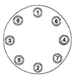
9. Match the power cable lugs to the corresponding terminal strip posts and secure each lug to the corresponding post with a flat washer, lock washer, and hex nut.
10. Replace the motor hand hole cover and o-ring, and secure it with socket head capscrews and hi-collar lockwashers.
11. Carefully slide the tram motor into position in the tram case. The end of the motor must be completely flush against the primary planetary adapter plate.
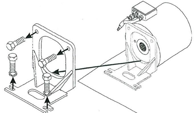
12. Position the tram motor bracket (Fig. 191) against the motor. The lower half of the bracket must be flush against the motor and upper bracket must be flush against the tram case. Reposition the tram motor until the bracket can be properly positioned.
13. Insert and tighten the socket head capscrews to secure the tram motor bracket to the tram motor.
14. Insert and tighten the hex head capscrews and disc lock washers to secure the tram motor bracket to the tram case.
15. Insert the two cooling water fittings into the cooling water ports located on the top left and right corners of the tram motor.
16. Attach the cooling water hoses to the two cooling water fittings located on the top left and right corners of the tram motor.
17. Remove the hex head capscrews and hi-collar lock washers that secure the input shaft access cover to the motor housing.
18. Remove the input shaft access cover and its O-ring.
19. Slide the input shaft through the tram motor and into the tram planetary primary gear (the input shaft end without the threaded hole should be inserted first). The shaft may require some adjusting so that its splined end fits into the gear.
20. When the drive shaft is correctly positioned in the motor, install the o-ring onto the input shaft plug and then insert the plug into the motor.
21. Insert the retaining ring to secure the input shaft plug inside the tram motor.
22. Replace the input shaft access cover and its O-ring on the motor housing. When replacing the input shaft access cover and its capscrews, carefully insert the tram motor cooling water bypass hose into the bypass hose clamp. The clamp is secured to the tram motor by the access cover’s lower capscrew. Secure the cover with hex head capscrews and hi-collar lock washers.
23. Replace the tram rub rail between the two adjacent rub rails and secure it with the two rub rail pins.