3 minute read
Gathering head foot shaft.............................................5


BI016912-04 (EN-US)
Advertisement
gathering head foot shaft removal Gathering head foot shaft removal and installation
To remove the gathering head foot shaft:
1. Lower the gathering head until it touches the floor.
2. Position the conveyor tail section directly behind the miner so that it is level with the floor.
3. Raise the cutter head assembly to its highest position. Place blocking underneath the cutter head assembly and lower the cutter head assembly onto the blocking.
WARNING! You could be seriously injured or killed by falling loads. Observe the safe working load limits of blocking devices.
4. Slowly advance the conveyor chain until a connecting link appears on the gathering head entrance pan.
5. Disconnect the trailing cable to de-energize the miner. Follow all Federal and mine regulations for lockout/tagout.
WARNING! Follow all federal and mine lockout/tagout regulations. Failure to do so could result in machine damage or serious injury or death to personnel.
6. Loosen tension on the conveyor chain as much as possible (see Conveyor chain adjustment procedure in the Adjustment procedures section of this chapter).
7. With conveyor chain tension removed, remove the connecting link pins and the connecting link.
8. The conveyor chain should now be separated. Move the two pieces of the conveyor chain out of the way to allow for easier removal of the gathering head foot shaft.
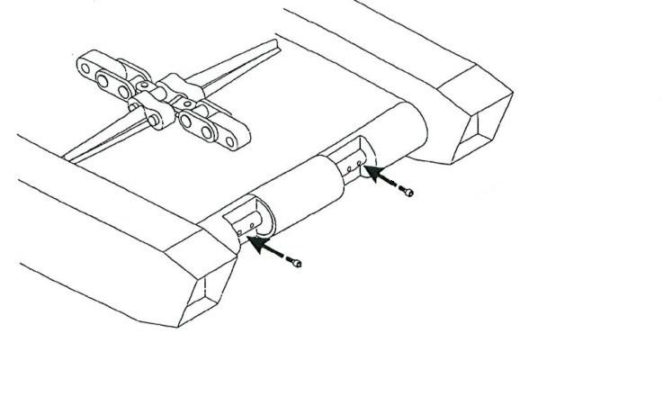
9. Remove the hex head capscrews and lock washers that secure the foot shaft cover to the gathering head and remove the foot shaft cover.
10. Locate the two collars on the foot shaft and remove the hex head capscrews that secure each of the collars to the foot shaft. When the capscrews are removed, the flex lock nuts will fall free from the other side of the collar. Retrieve these nut and hand tighten them onto their capscrews for safe keeping. Remove both collars from the foot shaft.
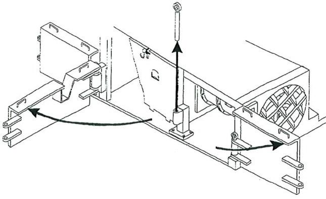
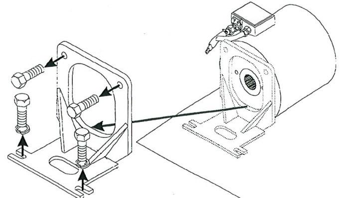
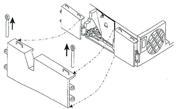
14. Slide the foot shaft couplings (Fig. 181) from the ends of the foot shaft toward the sprocket in the center. Once the couplings have been moved, the foot shaft is disconnected from the gear case bevel pinions.
15. The foot shaft can now be removed from the gathering head.
Fig. 181: Foot shaft removal
Hex head capscrews Gear case bevel pinion
Flex lock nuts
gathering head foot shaft installation
Foot shaft coupling Foot shaft collar
To install the gathering head foot shaft:
1. Slide a coupling onto each end of the foot shaft (Fig. 181).
2 Inspect the snap rings on both output shaft seal retainers.
3. Insert the gathering head foot shaft into position between the two gathering head gear case bevel pinions.
IMPORTANT! Position the foot shaft so its sprocket will engage the conveyor chain links when the chain is reconnected.
4. Align the foot shaft splines with the bevel pinions’ splines.
5. Slide the right coupling over the foot shaft spline onto the bevel pinion splines until it touches the gear case seal carrier. Repeat with the left coupling.
6. Place a collar onto each end of the foot shaft so that the collars keep the couplings secure against the gear case seal carriers, bridged between the foot shaft and bevel pinion.
7. Insert and tighten the hex head capscrews through both halves of each collar and into the flex lock nuts to secure the collars to the foot shaft.
8. Replace the foot shaft cover.
9. Insert and tighten the hex head capscrews and lock washers to secure the foot shaft cover to the gathering head.
BI016912-04 (EN-US)
10. Reattach the two ends of the conveyor chain by replacing the connecting link. Secure the link.
11. Tighten the conveyor chain to the proper tension (see Conveyor chain adjustment procedure in the Adjustment procedure section of this chapter).
IMPORTANT! Improper conveyor chain tension can lead to excessive wear, mechanical problems, and miner downtime. Always keep the convey-
or chain at proper tension.