7 minute read
Gathering head gear case............................................5


BI016912-04 (EN-US)
Advertisement
gathering head gear case removal Gathering head gearcase removal and installation
To remove the gathering head gear case:
1. Lower the conveyor tail section until it is level with the floor. Lower the gathering head until it touches the floor.
2. Raise the cutter head assembly to its highest position. Place blocking underneath the cutter head assembly. Lower the cutter head assembly onto the blocking.
WARNING! You could be seriously injured or killed by falling loads. Observe the safe working load limits of blocking devices.
3. Disconnect the trailing cable to de-energize the miner. Follow all Federal and mine regulations for lockout/tagout.
WARNING! Follow all federal and mine lockout/tagout regulations. Failure to do so could result in machine damage or serious injury or death to personnel.
4. Remove the gathering head motor’s side cover by removing the hex head capscrews and lock washers that secure the side cover to the gathering head assembly.
5. Remove the cover to expose the end of the motor.
6. Remove the square-headed pipe plug on the end of the gathering head motor.
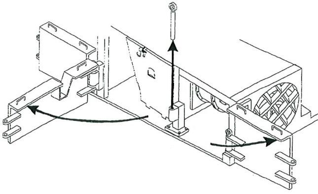
7. Remove the retaining ring that secures the shaft end plug inside the motor housing (Fig. 175).
8. Using a slide hammer, pull out the drive shaft end plug.
9. Pull the drive shaft from the motor and store in a safe place.
10. Replace the pipe plug into the end of the motor.
Fig. 175: Motor shaft removal
Drive shaft end plug O-ring
Retainer ring
Drive shaft
11. Remove the CLA to expose the gathering head gear case (see CLA removal and installation procedure in this chapter).
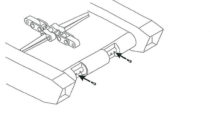
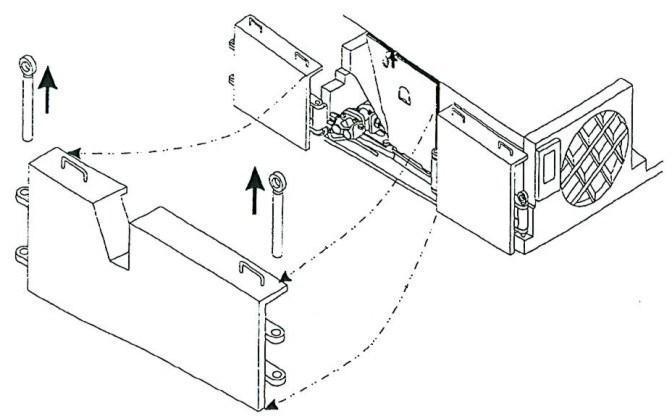
12. Remove the hex head capscrews and lock washers that secure the upper deck cover (Fig. 176) to the gathering head assembly. Remove the upper deck cover to expose the gear case and the drive shaft end of the motor.
13. Remove the hex head capscrews and lock washers that secure the lower deck cover (Fig. 176) to the gathering head assembly and remove the lower deck.
Fig. 176: Deck covers
Upper deck cover
Lower deck cover
14. Loosen tension on the conveyor chain as much as possible (see Conveyor chain adjustment in the Adjustment procedures section of this chapter).
15. Separate the conveyor chain and remove the gathering head foot shaft (see the Foot shaft removal and installation procedure in this chapter).
16. Connect the trailing cable to energize the miner.
17. Raise the gathering head to its highest position. Place blocking underneath the gathering head and lower the gathering head onto the blocking.
WARNING! You could be seriously injured or killed by falling loads. Observe the safe working load limits of blocking devices.
18. Disconnect the trailing cable to de-energize the miner. Follow all Federal and mine regulations for lockout/tagout.
WARNING! Follow all federal and mine lockout/tagout regulations. Failure to do so could result in machine damage or serious injury or death to personnel.
BI016912-04 (EN-US)
19. Remove the drain plugs from the underside of the gathering head gear case and completely drain the gear case lubricant.
20. Replace the drain plugs into the underside of the gear case.
21. Connect the trailing cable to energize the miner.
22. Raise the gathering head off the blocking, remove the blocking, and lower the gathering head until it touches the floor.
23. Disconnect the trailing cable to de-energize the miner. Follow all Federal and mine regulations for lockout/tagout.
WARNING! Follow all federal and mine lockout/tagout regulations. Failure to do so could result in machine damage or serious injury or death to personnel.
24. Disconnect, tag, and cap the four lubrication connections from the gathering head gear case.
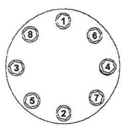
25. Remove the socket head capscrews (Fig. 177) that secure the motor to the gear case adapter plate.
26. Remove the motor and clean out the cavity.
27. Remove the hex head capscrews that secure the gathering head gear case pot to the mounting plate.
28. Remove four wedge bolts and remove four wedge blocks.
29. The gathering head gear case is now unattached and can be removed from its position in the gathering head.
Fig. 177: Gear case removal
Plugs Socket head capscrews (gear case to adapter plate) Adapter plate
Lubrication lines Hex head capscrews (gear case to mounting plate)

gathering head gear case removal
To install the gathering head gear case:
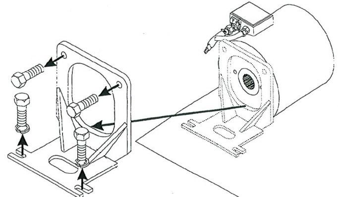
1. Insert a new gear case-to-motor seal between the adapter plate and the gear case (Fig. 178). When the gear case is inserted into the gathering head and the transfer case is positioned against the gathering head motor, the seal should be located between the surfaces of the motor and the gear case.
2. Carefully insert the gathering head gear case into position in the gathering head assembly.
3. Insert and tighten the hex head capscrews and lock washers to secure the gear case pot to its mounting plate.
Fig. 178: Gear case mounting
Gear case adapter plate
Gear caseto-motor seal

Hex head capscrews
4. Install the motor and align the four holes on the corners of the adapter plate with the four attachment bolt holes on the gear case side of the motor.
5. Apply Loctite 242 (blue) to the four socket head capscrews.
6. Insert and tighten the four socket head capscrews to secure the gear case adapter plate to the motor.
7. Attach the four lubrication connections to the gathering head gear case.
8. Attach the rose gun to the lower ports located adjacent to the gathering head side cover and fill the gathering head gear case to the proper level with lubricant. Check the gear case lubricant level.
IMPORTANT! The bottom ports on the high speed input cases are the fill lines. The top ports on the high speed input cases are the check lines.
9. Examine the gathering head gear case in various places for signs of leaking lubricant that identify improper installation or gear case damage.
BI016912-04 (EN-US)
10. Install the gathering head foot shaft and reconnect the conveyor chain (see Foot shaft installation procedure in this chapter).
11. Tighten the conveyor chain to the proper tension (see Con veyor chain adjustment in the Adjustment procedures section of this chapter).
IMPORTANT! Improper conveyor chain tension can lead to excessive wear, mechanical problems, and miner downtime. Always keep the conveyor chain at proper tension.
12. Replace the lower deck cover (Fig. 179) onto the gathering head assembly and secure to the gathering head assembly by inserting and tightening the hex head capscrews and washers.
13. Replace the upper deck cover (Fig. 179) onto the gathering head assembly and secure by inserting and tightening the hex head capscrews and washers.
Fig. 179: Deck covers
Upper deck cover
Lower deck cover
14. Install the CLA onto the gathering head gear case turntable (see CLA removal and installation procedure in this chapter).
15..Remove the pipe plug from the end of the motor.
16. Slide the drive shaft through the gathering head motor and into the gathering head gear case (the drive shaft end without the threaded hole should be inserted first.) The shaft may require some adjustment so that its end fits into the gear case.
17. Install the o-ring into the channel on the shaft end plug (Fig. 180).
18. Insert the drive shaft end plug into position in the center of the motor.
19. Insert the retaining ring to secure the shaft end plug inside the motor housing.
Fig. 180: Drive shaft installation
Retainer ring O-ring

Pipe plug
Drive shaft end plug Drive shaft
20. Replace the pipe plug into the end of the motor.
21. Install fittings and re-hose water supply.
22. Replace the side cover onto the gathering head assembly.
23. Insert and tighten the hex head capscrews and lock washers to secure the side cover to the gathering head assembly.