7 minute read
Gathering head assembly ............................................5


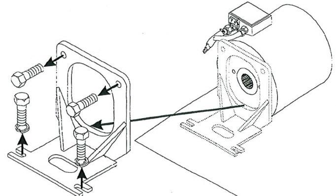
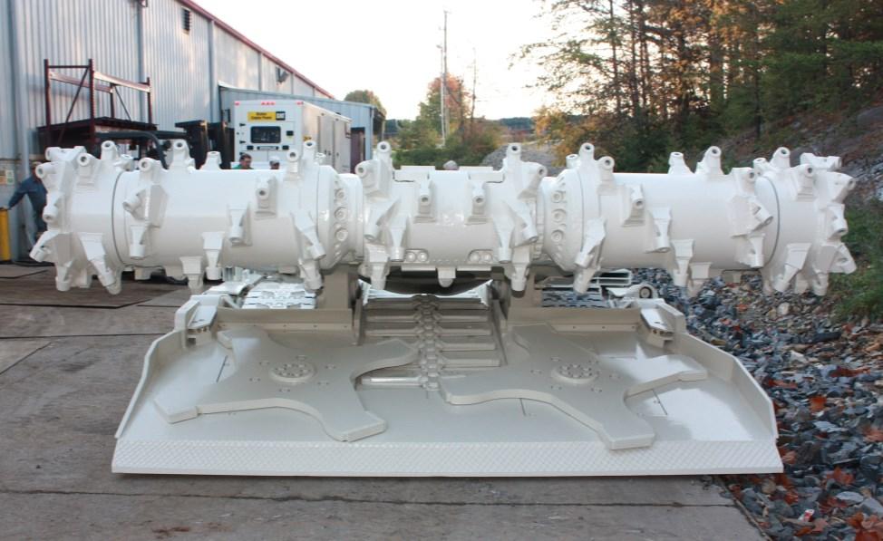
Fig. 168: Gathering head assembly Gathering head assembly
Advertisement
The gathering head assembly (Fig. 168) consists of the gathering pan, the continuous loading arms (CLAs), lift cylinders, and drive motors.
Lift cylinder location Gear case (under CLA) Foot shaft location CLA key Continuous loading arms (CLA) (2)
gathering head assembly removal To remove the gathering head assembly
1. Lower the conveyor tail section until it is level with the floor. Lower the gathering head until it rests on the floor. Place blocking under the rear of the gathering head to stabilize its position during and after removal of the pivot pins and disconnection of the lift cylinders.
2. Raise the cutter head to its highest point and place blocking underneath it. Lower the cutter head onto the blocking.
WARNING! You could be seriously injured or killed by falling loads. Observe the safe working load limits of blocking devices.
3. Disconnect the trailing cable to de-energize the miner. Follow all Federal and mine regulations for lockout/tagout.
WARNING! Follow all federal and mine lockout/tagout regulations. Failure to do so could result in machine damage or serious injury or death to personnel.
BI016912-04 (EN-US)
4. Double check that the cutter head is securely blocked.
5. Separate the conveyor chain and remove the foot shaft (see Foot shaft removal procedure in this chapter).
6. Remove the hex head capscrews and lock washers that secure each of the front rub rails to the tractor frame and open both front rub rails.
7. Remove the electrical power cables from the gathering head.
8. Disconnect, tag, and cap the motor cooling water and scrubber spray water hoses from the gathering head.
WARNING! You could be seriously injured or killed by falling loads. Do not remove the gathering head pivot pins unless the gathering head is securely blocked into a stationary position. Use extreme caution when removing the pivot pins.
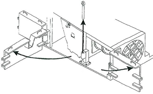
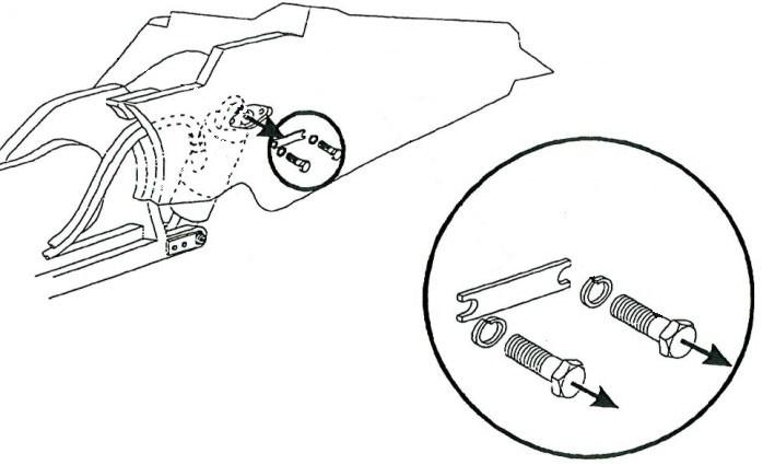
9. Remove the hex head capscrews and lockwashers that secure the right gathering head pivot pin retaining plate to the tractor frame (Fig. 169).
10. Remove the hex head capscrews and lock washers that secure the pin retaining plate to the gathering head pivot pin and remove the retaining plate.
Fig. 169: Gathering head pivot pin
Hex head capscrews (retaining plate to tractor frame) Pivot pin retaining plate Gathering head pivot pin
Hex head capscrews (retaining plate to pivot pin)
11. Using a slide hammer, pull the pivot pin.
12. Repeat steps 9 through 11 for the left gathering head pivot pin.
WARNING! You can be seriously injured or killed by falling loads. Do not disconnect the gathering head cylinder unless the gathering head is securely blocked. Use extreme caution when disconnecting the gathering head lift cylinder.
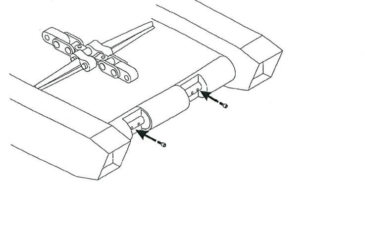
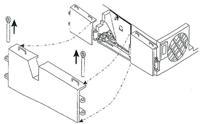
13. Remove the hex head capscrews and lock washers that secure the piston pin retaining bar on the right gathering head lift cylinder to the gathering head side panel and remove the retaining bar (Fig. 170).
14. Repeat step 13 for the left gathering head lift cylinder.
Fig. 170: Gathering head lift cylinder piston pin retaining bar
Piston pin
Lock washer
Gathering head lift cylinder Retaining bar
Hex head capscrew
15. Connect the trailing cable to energizer the miner.
WARNING! Stand clear of the blocked cutter head and gathering head assemblies during the contraction of the gathering head lift cylinders.
16. Slowly contract the lift cylinders until the piston ends come free from their gathering head clevises.
CAUTION! When separating the gathering head from the tractor frame, ensure that the disconnected ends of the conveyor chain smoothly slide out of the gathering head.
17. Lift the cutter head off the blocking and slowly tram the miner in reverse until the cutter head clears the backboard of the gathering head. ______________________________________________________________
BI016912-04 (EN-US)
gathering head assembly installation
To install the gathering head assembly:
1. Position the gathering head assembly at the front of the tractor frame. Block up the rear of the gathering head so that it’s pivot points are at the level of the tractor frame clevises.
WARNING! You could be seriously injured or killed by falling loads. Observe the safe working load limits of blocking devices.
CAUTION! When tramming the miner toward the gathering head, be careful that the conveyor chain and gathering head lift cylinders do not become pinched between the tractor frame and the gathering head.
2. Raise the cutter head assembly to its highest point.
3. Slowly tram the miner forward until it is close to the gathering head head assembly.
4. Thread the lower end of the conveyor chain into the gathering head assembly return pan so that the end appears on the footshaft return plate. Place the upper end of the conveyor chain down the front of the gathering head entrance pan.
5. Place blocking underneath the cutter head and lower the cutter head onto the blocking.
6. Disconnect the trailing cable to de-energize the miner. Follow all Federal and mine regulations for lockout/tagout.
WARNING! Follow all federal and mine lockout/tagout regulations. Failure to do so could result in machine damage or serious injury or death to personnel.
7. Connect the trailing cable to energize the miner.
WARNING! You could be seriously injured or killed by falling loads. Observe the safe working load limits of blocking and lifting devices and stand clear of the blocked cutter head and the gathering head during the gathering head lift extension.
8. Extend the gathering head lift cylinders so that the piston end bearings can be inserted into the gathering head lift cylinder clevises.
9. Disconnect the trailing cable to de-energize the miner. Follow all Federal and mine regulations for lockout/tagout.
WARNING! Follow all federal and mine lockout/tagout regulations. Failure to do so could result in machine damage or serious injury or death to personnel.
10. Insert the piston end bearing of the right gathering head lift cylinder into the gathering head clevis.
11. Using the hammer, insert the piston end pin through the aligned clevis bushings and the rod end bearing.
IMPORTANT! Insert the pin far enough to avoid obstructing the placement of the pin retaining bar.
12. Place the pin retaining bar over the end of the pin and insert and tighten the two hex head capscrews and lock washers that secure the piston pin retaining bar to the gathering head side panel.
13. Repeat steps 10 through 12 on the left gathering head lift cylinder.
CAUTION! Use caution when using the lift cylinders and stabilizer to adjust the alignment of the clevis and pivot pins.
14. Use the gathering head lift cylinders and tractor frame stabilizer to align the tractor frame clevis and the gathering head pivot points to make inserting pivot pins easier.
15. Gently tap the right gathering head pivot pin through the aligned tractor frame clevis and gathering head pivot bushings.
IMPORTANT! The pin must be inserted far enough so that it does not obstruct positioning of the retaining plate flat against the tractor frame.
16. Place the pivot pin retaining plate so that edge with two cutouts located in the corners is positioned against the backup strip. The edge of the plate with two cutouts and a hole for the pin’s grease fitting must be positioned over the pivot pin.
17. Insert and tighten the two hex head capscrews and lock washers to secure the pivot pin retaining plate to the gathering head pivot pin.
18. Insert and tighten the hex head capscrews and lock washers to secure the pivot pin retaining plate to the tractor frame.
19. Repeat steps 16 through 18 for the left gathering head pivot pin.
20. Replace the motor cooling water and scrubber spray water hoses onto the gathering head assembly.
21. Replace the electrical power cables onto the gathering head assembly.
BI016912-04 (EN-US)
22. Close the front rub rails and insert and tighten a hex head capscrew and lock washer to secure the front rub rail closed against the tractor frame.
23. Replace the foot shaft into the gathering head (see Foot shaft removal and installation procedure in this chapter) and reconnect the conveyor chain.