6 minute read
Drum drive motor..........................................................5


drum drive motor removal Drum drive motor
Advertisement
To remove the drum drive motor:
1. Lower the gathering head completely until it touches the floor. Lower the conveyor tail assembly until it is level with the floor.
2. Raise the cutter head assembly to its highest position. Place blocking underneath the cutter head assembly. Lower the cutter head assembly
WARNING! You could be seriously injured or killed by falling loads. Observe the safe working load limits of all blocking devices. Do not stand near the blocked cutter head.
3. Disconnect the two cooling water hoses from the top manifold. Plug the hose ends to keep them clean.
WARNING! Follow all Federal and mine lockout/tagout regulations and procedures. Failure to do so could result in machine damage or serious injury or death to personnel.
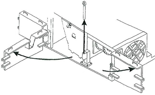
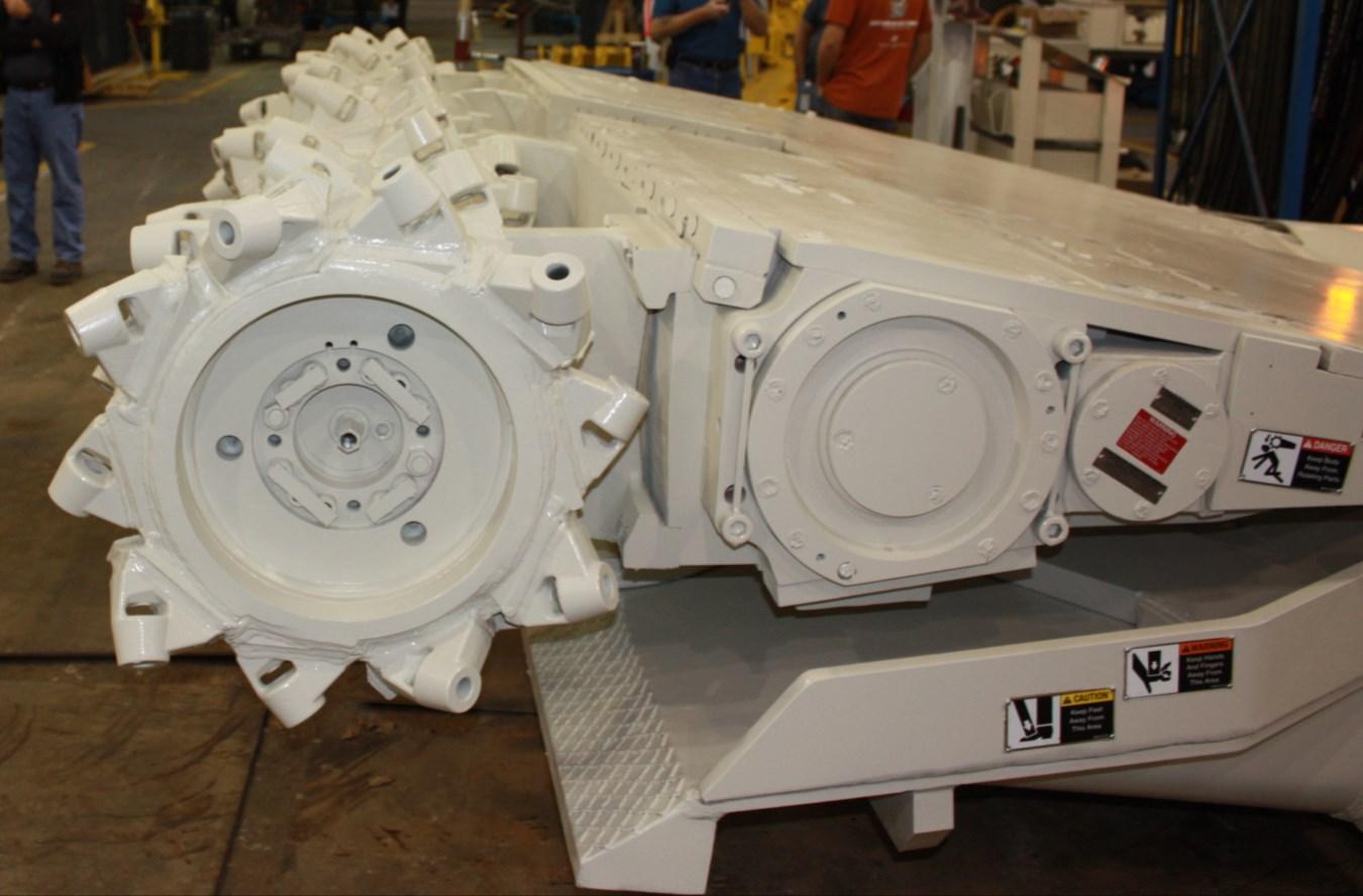
Fig. 163: Drum drive motor
Drum drive motor
BI016912-04 (EN-US)
4. Disconnect the trailing cable to de-energize the miner. Follow all Federal and mine lockout/tagout regulations. Disconnect the two cooling water hoses from the top manifold. Plug the hose ends to keep them clean.
5. Remove the hex head bolts and lock washers that secure the manifold.
6. Remove the two manifolds to expose the top of the motor. Two o-rings on the top and bottom will be visible. Secure o-rings for use in re-installation.
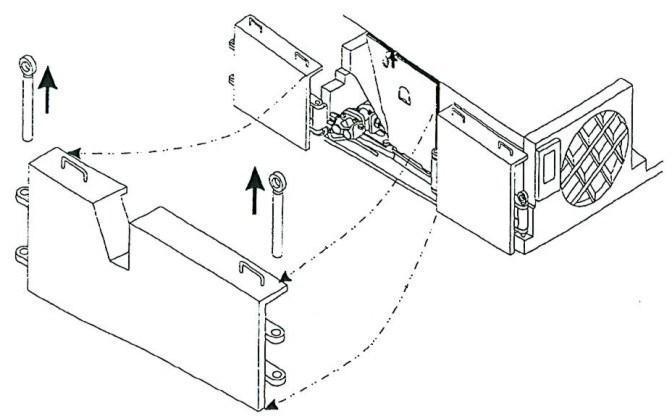
7. Remove the flat bar connecting the hex head capscrews and lockwashers that secure the side motor cover.
8. Remove the cover (Fig. 164) to expose the side of the motor and the motor’s junction box.
WARNING! You could be seriously injured or killed by falling loads. Observe the working load limits of lifting and blocking devices.
Fig. 164: Cover removal
Hex head bolts (4) Manifold
Flat bar Capscrews (8)
9. Remove the cutter motor shaft.
10. Place blocking under the motor to keep it supported when it becomes free from the cutter boom. 11. Remove the hex head caps crews and lockwashers that secure the junction box cover (Fig. 165).
12. Remove the cover and O-ring.
13. Locate the three taped power connections.
14. Strip off the three layers of tape covering these lug connections.
IMPORTANT! Before detaching these lugs, mark the wires to facilitate reconnection during motor installation.
15. Tag the lugs for correct reconnection then remove the hex head capscrew, flat washer, lock washer and hex head nut that secure the three power cable lugs to the three motor lugs.
16. Remove the socket head capscrews and lockwashers that secure the stuffing box’s half-moon clamp to the junction box.
17. Remove the clamp and slide the stuffing box out of the junction box. The power cable should be completely disconnected from the motor.
WARNING! While this power cable is detached from the motor, the trailing cable should not be reconnected to energize the miner. Damage to the miner, personal injury or death could result.
18. To prevent damage to the power cable lugs and gland assembly, cover the power cable and secure it to the miner in a safe location.
19. To protect the motor’s electrical connections, replace the motor junction box cover and secure it using hex head capscrews and lock washers.
BI016912-04 (EN-US)
WARNING! You could be seriously injured or killed by falling loads. Observe the safe working load limits of all lifting devices.
20. Remove the four socket head capscrews that secure the cutter drive motor to the cutter gear case (Fig. 165).
21. Remove motor and remove bottom manifold. Secure o-rings ( 2 ea.). Manifolds (top and bottom) do not come on exchange motors.
22. Remove plates on exchange motor (installed to cooling ports) and re-install on motor removed.
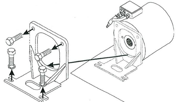
Fig. 165: Drum drive motor
Hex head bolts (4) Manifold
Capscrews (8)
drum drive motor installation To install the drum drive motor:
WARNING! Federal law requires that mining equipment electrical connections must be inspected by a certified electrician before the equipment can be operated.
WARNING! This procedure involves attaching an electrical power cable to the cutter head drum drive motor. The trailing cable must be disconnected to safely perform this operation or serious injury or death will result.
1. Block up cutter head drum drive motor into position against the rear of the boom so that the motor’s mounting holes align with the boom’s threaded motor mounting holes.
WARNING! You can be seriously injured or killed by a falling load. Follow the safe working load limits of all blocking devices.
2. Insert the four bolts through the motor mounting holes and hand tighten them into the boom’s threaded motor mounting holes
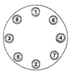
3. Torque the four bolts to approximately 1,800 ft-lbs (see bolt installation procedure in this chapter) to secure the drive motor to the boom.
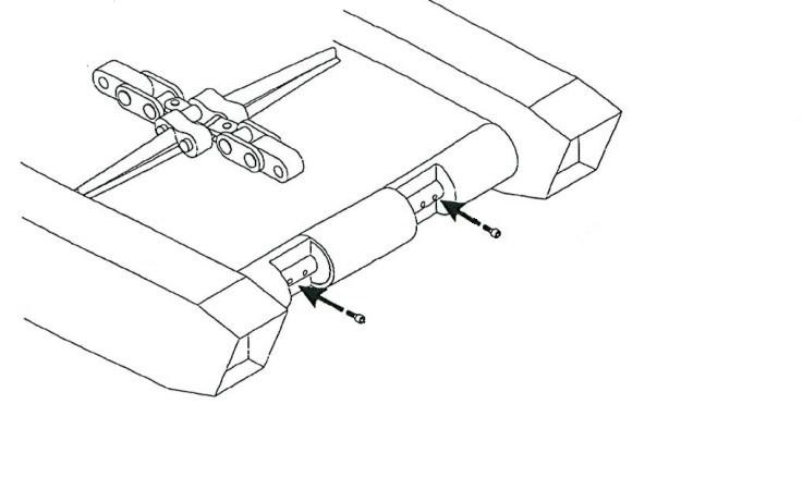
4. Attach rear support mount to motor with bolts and lock washers . Torque bolts to proper setting (see Torque tables in Chapter 6).
5. Install the two motor cooling water fittings into the front and rear cooling water ports of the motor.
6. Attach the two motor cooling water hoses to the fittings.
7. Using a socket wrench, remove the four hex head capscrews and lock washers that secure the junction box cover.
8. Remove the cover and O-ring.
BI016912-04 (EN-US)
9. Insert the three lugs of the power cable (with gland and stuffing box already installed) into the motor’s junction box.
10. Replace the stuffing box’s half-moon clamp in its channel to secure the stuffing box in the junction box.
11. Tighten the two socket head capscrews to secure clamp to the junction box.
12. Inside the junction box, locate the motor’s lug connections.
13. Match the motor lug connections to the corresponding power cable lugs.
14. Attach the first motor lug to its corresponding power cable lug by inserting a hex head capscrew through the motor lug, through the power cable lug, through a flat washer, and through a lock washer. Secure the capscrew with a hex nut.
15. Repeat this step for the other two lugged connections.
16. When all three connections have been secured, wrap each of the three connections with a layer of rubber tape, then a layer of black tape and then a layer of glass tape.
17. Replace the junction box O-ring and cover.
18. Insert the four hex head capscrews and lockwashers to secure the junction box cover and tighten using a socket wrench.
19. An MSHA certified electrician must inspect all work and check for permissibility.
20. Replace the top motor cover.
21. Tighten the hex head capscrews and lock washers to secure the top cover.
22. Replace the side motor cover.
23. Install the drum drive shaft and the cutter head drum drive torque limiting clutch (see Drum drive torque limiting clutch removal and installation procedure in this chapter).
24. Replace the debris guard (optional) under the retaining strap. The holes of the guard and strap should align with the threaded holes in the motor top cover.
25. Tighten the hex head capscrews and lock washers to secure the debris guard and its retaining strap to the top motor cover.