2 minute read
End cutter drum............................................................5


End cutter drum
Advertisement
end cutter drum removal To remove the end cutter drum:
1. Lower the gathering head completely until it touches the floor. Lower the conveyor tail assembly until it is level with the floor.
2. Raise the cutter head assembly to its highest position. Place blocking underneath the cutter head assembly and lower the cutter head assembly onto the blocking.
WARNING! You could be seriously injured or killed by falling loads. Observe the safe working load limits of lifting devices and keep a safe distance from suspended loads.
3. Disconnect the trailing cable to de-energize the miner. Follow all Federal and mine lockout/tagout regulations.
WARNING! Follow all Federal and mine lockout/tagout regulations and procedures. Failure to do so could result in machine damage or serious injury or death to personnel.
4. Drain the gear case oil before removing the drums.
5. Remove the lock tabs tack welded to the capscrews using a cutting torch.
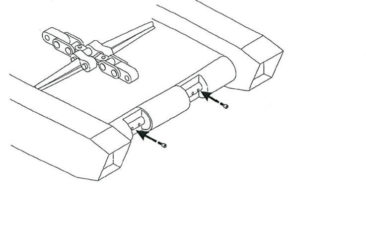
Fig. 160: Lock tabs tack welded to capscrews
Lock tab welded in place
Access to center drum input shaft Oil drain plug
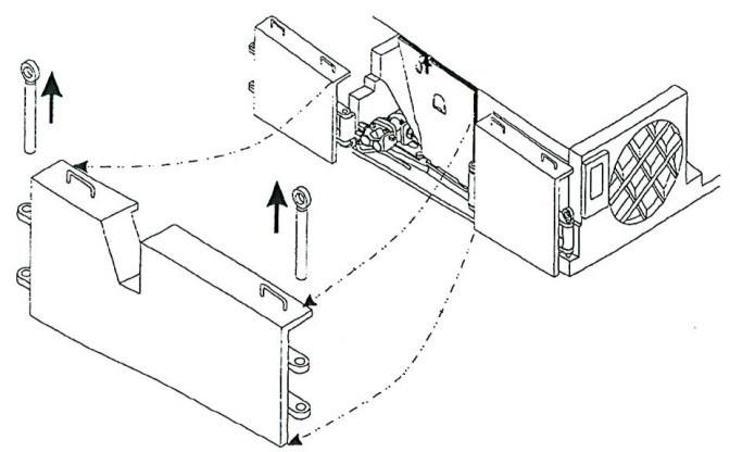
6. Remove the long capscrews and nuts on the two alignment dowels which secure the end drum to the cutter drum drive assembly.
7. Remove plug and center drum input shaft.
8. Remove the drum by sliding it off the hub.
9. Remove the drum alignment key (Fig. 161) and store for reinstallation. ______________________________________________________________
BI016912-04 (EN-US)
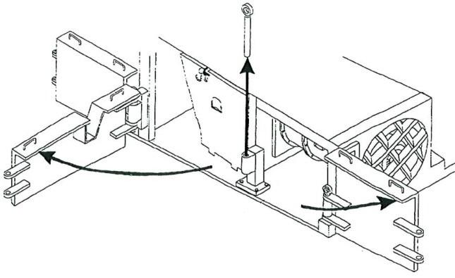
Fig. 161: Drum alignment key

Drum alignment key
WARNING! You could be seriously injured by falling loads. Use extreme caution when working near suspended loads.
end cutter drum installation
To install the end cutter drum:
1. Locate the timing arrows (Fig 162) on the intermediate drum and the end drum about to be installed. The end drum must be installed so that its timing arrow is directly adjacent to the intermediate drum timing arrow.
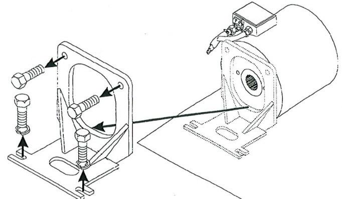
Fig. 162: Intermediate drum timing arrows
Timing arrow on intermediate drum Timing arrow on intermediate drum

2. Insert drum alignment key.
3. Slide the end drum onto the cutter drum drive gear case.
4. Install the plug and center drum input shaft. Add oil as necessary.
5. Tighten the long capscrews and nuts onto the two alignment dowels which secure the end drum to the cutter drum drive assembly.
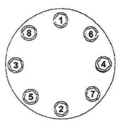
6. Torque the capscrews to 350 lb.-ft. Tack weld the lock tabs.