5 minute read
Boom pivot pin..............................................................5


Advertisement
To remove the boom pivot pin:
1. Lower the conveyor tail section until it is level with the floor and gathering head and cutter head until they rest on the floor.
2. Disconnect the trailing cable to de-energize the miner. Follow all Federal and mine regulations regarding lockout/tagout procedures.
WARNING! Follow all Federal and mine regulations regarding lockout/tagout procedures. Failure to do so may result in serious injury or death.
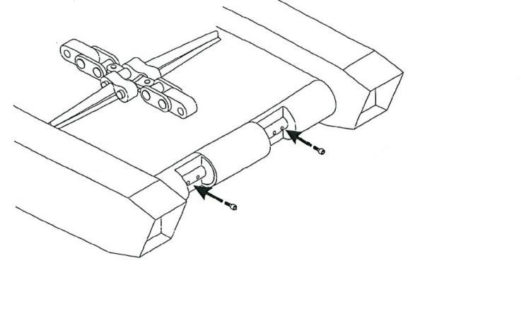
3. Locate the miner’s front rub rail and remove the hex head capscrew and lock washer that secures the rub rail to the tractor frame.
4. Open the front rub rail (Fig. 155).
Fig. 155: Front rub rail
Capscrew and lock washer
Capscrew and lock washer
Tram rub rail
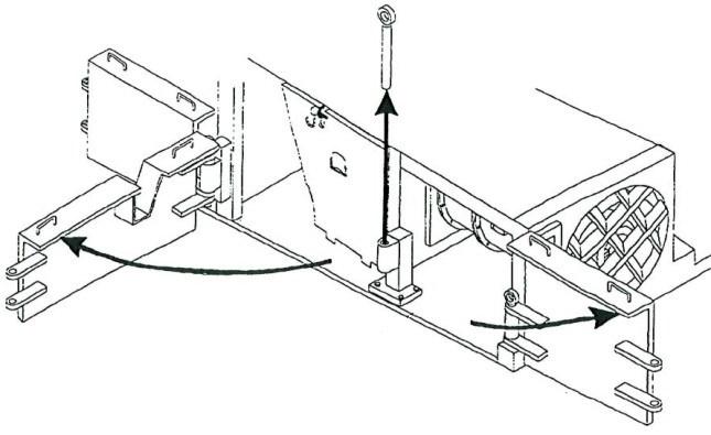
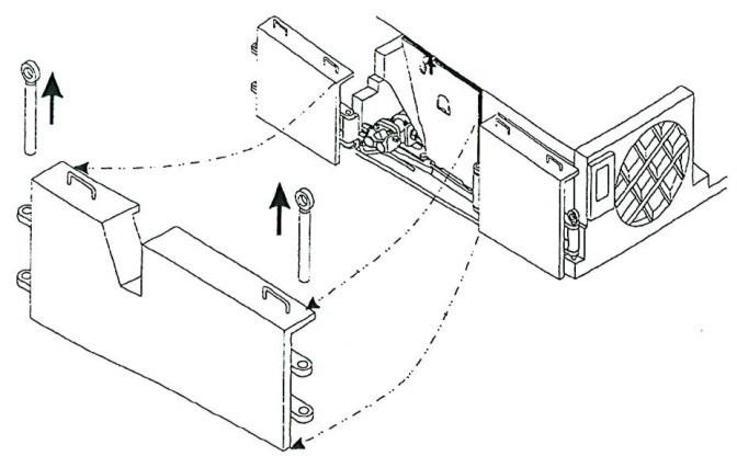
5. Locate the front idler take-up jack bracket assembly (Fig. 156), which is mounted directly to the rear of the idler shim channel.
6. Pull the flip pin from the half link to release the take-up jack bracket from the tractor frame.
7. Lower the end of the bracket until it clears the half link and pull the bracket straight out to remove it from the tractor frame.
IMPORTANT! Pressure from the cutter boom onto the pivot pin can make its removal very difficult. The shear cylinders can be used to find the boom position that puts the least pressure on the pin.
CAUTION! When the pivot pin pull point is found, block the cutter boom to prevent it from dropping or moving when the pivot pin is removed.
BI016912-04 (EN-US)
Fig. 156: Half link
Tale-up jack bracket
Half link
Flip pin

8. Locate the end of the boom pivot pin in the area from which the take-up jack bracket was removed.
9. Remove the hex head capscrews and lockwashers that secure the boom pivot pin retaining plate to the tractor frame.
10. Remove the pin retaining plate and its support block.
11. Insert a slide hammer adapter into the threaded hole in the end of the boom pivot pin.
IMPORTANT! Pressure from the cutter boom onto the boom pivot pin can make its removal very difficult. The shear cylinders can be used to find the boom position that puts the least pressure onto the pin. This position can be determined by striking the pin, slightly contracting or extending the shear cylinder, then striking the pin again and comparing the “ring”; as boom pressure on the pin decreases, the “ring” of the pin when it is struck becomes lower. When the “ring” of the pin becomes short and low, pin removal is much easier.
CAUTION! Use extreme caution when adjusting the boom with the shear cylinder to find the pivot pin’s pull point.
12. When the pivot pin’s pull point is found, block the cutter boom to keep it from dropping or moving when the pin is pulled.
13. Attach the slide hammer to its adapter and pull the boom pivot pin.
boom pivot pin installation
To install the boom pivot pin:
1. Position the boom pivot pin so that the end with the two flats (the end without the adapter) is inserted first. The single flat of the pin’s opposite end must face the four retaining plate holes.
IMPORTANT! On the back of the tractor frame clevis there is a welded strap that keeps the boom pivot pin from rotating. One of the flats of the boom pivot pin must parallel this strap or the pin cannot be completely inserted.
2. Use the hammer to insert the boom pivot pin through the aligned tractor frame clevis and boom pivot bushings.
IMPORTANT! If it is extremely difficult to insert the boom pivot pin through the aligned tractor frame clevis and boom pivot bushings, extend or contract the shear cylinders to improve the alignment between the clevis and boom.
CAUTION! Use extreme caution when adjusting the clevis and boom alignment with the shear cylinders.
3. Replace the support block over the four threaded holes in the tractor frame.
4. Place the retaining plate onto the support block. The end of the retaining plate L-extension should be positioned against the flat of the boom pivot pin.
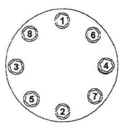
5. Insert and tighten the hex head capscrews lockwashers to secure the boom pivot pin retaining plate to the tractor frame.
BI016912-04 (EN-US)
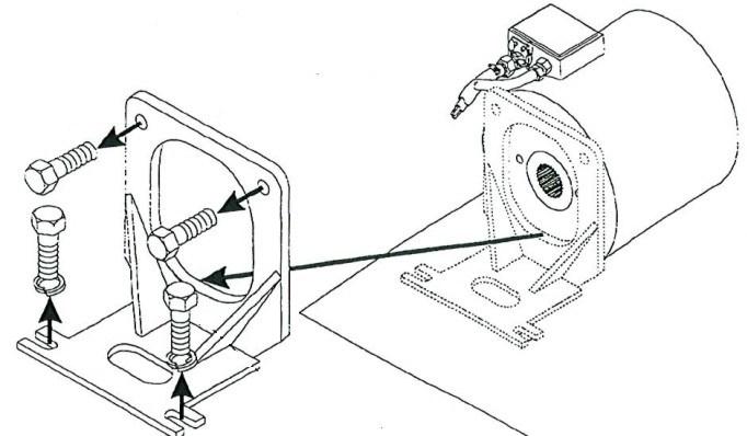
To install the boom pivot pin (reference Fig. 157):
1. If not already installed, install a bushing into the boom arm by pressing or shrinking the bushing into the boom arm. Check to insure that the pin will rotate freely in the bushing. It may be necessary to polish the bushing to allow the pin to rotate freely.
2. Install outside caps in frame, making sure that bolt holes are horizontal. Place the boom in the frame.
3. Apply anti-seize type lubricant to the straight area of the pin prior to installation into boom arm. Install the pin into the boom arm through the inside of the frame. Make sure the holes in pin align properly with the holes in the outside cap and grease porting is toward the outside of the machine.
4. Install installation cap into inside of the frame making sure that holes are aligned. Install bolts and nuts making sure that the4 outside cap and pin are located correctly. Tighten the bolts and nuts by alternating from on to the other. Tighten as tight as possible.
5. Remove bolts and nuts and replace installation cap with the inside cap making sure that the unthreaded holes line up with the pin and the outside cap holes before install and tightening nuts and bolts. Alternate from on bolt to the other when tightening. Tighten to approximately 600 ft-lbs. Check for tightness with the first eight hours of operation and occasionally thereafter.
6. Replace the take-up jack bracket assembly into the tractor frame and secure it by inserting the flip pin through the half link.
7. Close the front rub rail.
8. Insert and tighten the hex head capscrews and lock washers to secure the closed front rub rail against the tractor frame.