4 minute read
Center cutter drum .......................................................5


center cutter drum removal Center cutter drum
Advertisement
To remove the center cutter drum (Fig 158):
WARNING! Replacement of the cutter head center drum involves working around a raised cutter head assembly. Never work under any raised assembly without proper blocking. Always block between the raised assembly and the tractor frame in addition to between the raised assembly and the floor.
WARNING! This procedure involves disconnecting and reconnecting the miner’s trailing cable. Always be aware of whether or not the miner is energized. Never perform maintenance on an energized miner.
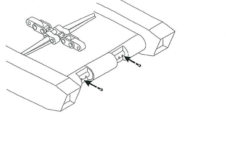
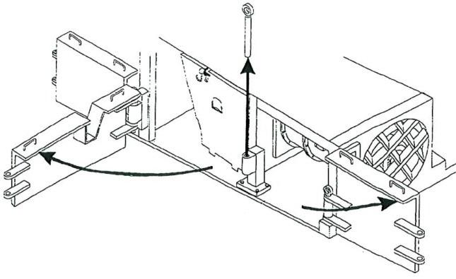
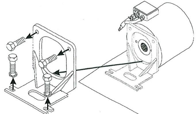
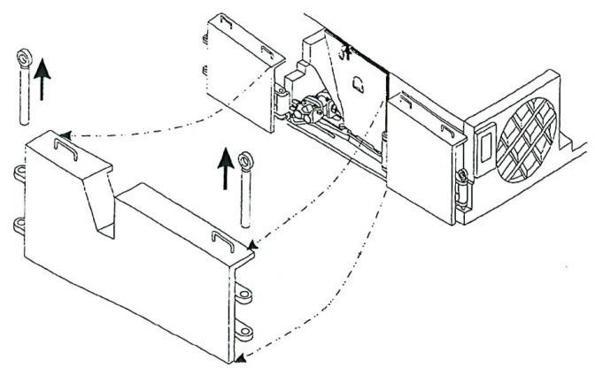
Fig. 158: Center cutter drum removal/installation (typical shown)
Center drum Drum seam Strap Capscrews
Alignment key (square ends)
Capscrews Retainer (strut bolts)
Strap
BI016912-04 (EN-US)
1. Lower the gathering head completely until its touches the floor. Lower the conveyor tail assembly until it is level with the floor.
2. Rotate the cutter head slowly until one of the center drum seams (Fig. 158) appears directly in front and one appears directly in rear of the cutter head.
3. Lower the cutter head assembly until it touches the floor.
4. Disconnect the trailing cable to de-energize the miner. Follow all Federal and mine lockout/tagout regulations.
WARNING! Follow all Federal and mine lockout/tagout regulations and procedures. Failure to do so could result in machine damage or serious injury or death to personnel.
CAUTION! Make sure the lifting device is capable of lifting the drum weight. Use care when handling the cutter drum.
DANGER! Never work under any raised assembly without proper blocking.
5. Remove the socket head capscrews securing the front seam of the center drum.
6. Remove the socket head capscrews securing the rear seam of the center drum.
7. Collect the retaining plates for the center drum’s capscrews. Store the retaining plates in a safe place for a center drum reassembly.
8. Attach chains to the upper half of the center drum. The chains should be capable of supporting the entire weight of the upper half of the center drum.
9. Using the pry bar and other necessary force, break the seal between the center drum so that the bottom half is free from the top half.
10. Using an appropriate lifting device, connect the chains on the upper half of the center drum.
12. Using an appropriate lifting device, lift the upper half of the center drum off the cutter head assembly. The cutter head and the lower half of the center drum should remain on the floor.
center cutter drum installation WARNING! Serious injury or death can result from falling loads. Observe the safe working load limits of lifting devices and keep a safe distance from suspended loads.
13. Connect trailing cable energize the miner.
14. Slowly raise the cutter head assembly until it is completely clear of the lower half of the center drum.
15. Slowly tram the miner backwards away from the suspended upper half and the resting lower half of the center until the cutter head assembly is completely clear of both of these pieces.
To install the center cutter drum (Fig. 158):
WARNING! You could be seriously injured or killed by falling loads. Observe the safe working load limits of lifting devices and keep a safe distance from suspended loads.
1. Slowly lower the cutter head assembly into the bottom half of the center drum. The bottom drum drive keys should fit into the interior of the lower half of the center drum.
WARNING! Stand clear of the cutter head assembly and the unsecured upper half of the center drum while lowering it.
2. Using an appropriate lifting device, slowly lower the upper half of the center drum onto the cutter head assembly. The top drum drive keys should fit into the underside interior of the upper half of the center drum.
3. Disconnect the chains that supported the upper half of the center drum.
4. Remove the chains from the upper half of the center drum.
BI016912-04 (EN-US)
5. Disconnect the trailing cable to de-energize the miner. Follow all Federal and mine lockout/tagout regulations.
WARNING! Follow all Federal and mine lockout/tagout regulations and procedures. Failure to do so could result in machine damage or serious injury or death to personnel.
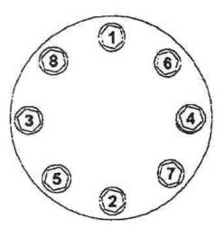
6. Insert the socket head capscrews into the holes in the top half of the drum through the alignment keys and through the bottom half of the drum. Use the following steps to equally distribute the torque over the center drum (Fig. 159):
Starting with the pair of capscrews at the right front of the center drum, place a retaining plate under the bottom half of the drum where the capscrews emerge and thread the capscrews into the retaining plate.
Alternating from front to back and moving from right to left, repeat this threading process on the other nine pairs of capscrews and nine retaining plates.
When all capscrews have been inserted into their retaining plates, start with the paired capscrews on the right of the front seam of the center drum and torque.
Proceed to the paired capscrews on the back right seam of the center drum and torque.
Alternating from front to back and moving from right to left, torque the eight remaining pairs of capscrews into their retaining plates.
7. Double check that all bolts have been properly torqued.