3 minute read
Cutter motor feedback..................................................5


Cutter motor feedback adjustment
Advertisement
The tram motor speed voltages are limited in the forward direction when the cutter motors are running. How much the tram speed is limited is controlled by the load on the cutter motors. When the load is light, as in a clean-up operation, the tram speed is less limited that when there is high cutter motor loading, as in a sumping operation. The cutter motor loading is monitored by using a current transformer, CT3, in a phase lead.
This cutter motor feedback is connected to the tram interface to control the tram motor speed voltages. The “clean-up” and “sump” tram voltages are factory set. It may be necessary to adjust these voltages to suit the actual mining conditions.
Reference Fig. 151: Tram interface and Fig. 152: SCR tram drive.
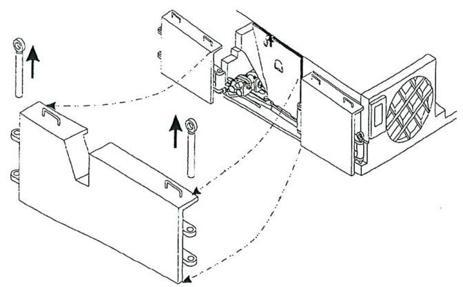
Open the tram case and access the traction case.
Current Generator: A current generator is available which can be used to simulate the secondary current in the feedback current transformer, CT3. The current generator needs to be connected to 120 vac. This can be tapped at terminal numbers 14 and 79 on the tram interface terminal strip (Fig. 151).
Remove the feedback wires number 196 and 197 from the tram interface terminal strip and connect the output of the current generator (flat cable) to the tram interface terminals 196 and 197. Be sure the power switch is off and the adjustable dial is set at zero.
Volt-Ohm Meter:
To check the left tram reference voltage connect VOM to tram interface terminal 41 pos. and D42 neg.
To check the right tram reference voltage connect VOM to tram interface terminal 51 pos. and D52 neg.
To check left armature voltage connect VOM to left SCR drive terminals A1 pos. and A2 neg.
To check right armature voltage connect VOM to right SCR drive terminals A1 pos. and A2 neg.
Before setting the clean-up and sump tram reference voltages, made sure the maximum high tram reference voltage is at 2.5 VDC to 3.0 VDC. This voltage is a fixed internal design and is not field adjustable.
Notes:
■ The left and right tram voltages must be adjusted separately.
■ The pump motor must be running for all tests/adjustments.
■ Always adjust clean-up voltage first.
■ If the miner does not track properly after the voltages are correctly adjusted do not readjust the voltages. Look for excessive looseness of a crawler track, binding in the traction drive train, or even missing cutter bits or bit holders.
To set the tram clean-up speed:
Apply 1.0 amp from the current generator to terminals #196 and #197 on the tram interface.
Move the tram control lever to full on forward.
A VOM armature voltage reading of 200 to 225 VDC should be on the SCR drive terminals A1 - A2. Note: The reference voltage will be approximately 1.25VDC.
Adjust the clean-up voltage using the adjustment screws marked “C” on the tram interface. Set the left and right tram voltages the same.
To set the sump speed:
Apply 4 amp from the current generator to terminals #196 and #197 on the tram interface.
Move the tram control lever to full on forward.
A VOM armature voltage reading of 85 VDC should be on the
SCR drive terminals A1 - A2.
NOTICE! The reference voltage will be approximately 0.55 VDC. Adjust the sump voltage using the adjustment screws marked “S” on the tram interface. Set the left and right tram voltages the same.
Reconnect the cutter motor feedback wires to the tram interface terminals #196 and #197 and reconnect tram control wires to the tram interface terminals and #51.
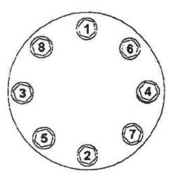
Fig. 151: Tram interface
Sump and clean-up voltage adjustments
120 VAC connection (14 & 79) Cutter motor feedback terminals (196 & 197) Reference voltage, left tram (41& D42)
Reference voltage, right tram (D52 & 51)
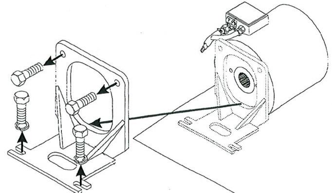
Fig. 152: SCR tram drive

DC motor connections (S1, S2, A1, A2) DC motor connections (S1, S2, A1, A2)