1 minute read
Grease take-up.....................................................5


IMPORTANT! Chain tension decreases as the tail section moves away from center. Check the chain tension when the tail is at an angle to confirm that it is properly adjusted.
Advertisement
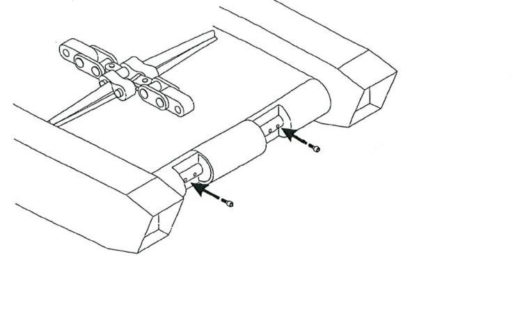
Fig. 149: Tail section position
Farthest from center Farthest from center
Chain tension adjustment - grease take-up
1. Lower the gathering head and cutter head until they touch the floor.
2. Position the conveyor tail section straight behind the miner and lower onto blocking until the tail is level with the floor. Follow all mine procedures for blocking.
WARNING! You could be seriously injured or killed by falling loads. Observe the safe working load limits of all blocking devices.
3. Disconnect the trailing cable to de-energize the miner. Follow all Federal and mine lockout/tagout regulations.
WARNING! Follow all Federal and mine lockout/tagout regulations and procedures. Failure to do so could result in machine damage or serious injury or death to personnel.
4. Pump grease into the take-up jack (Fig. 150) to extend the cylinder rod and remove pressure on the adjustment shims. Repeat this step on the other side.
5. Alternately, left and right, add shims to increase chain tension or remove shims to decrease chain tension. An equal number of shims must be used on each side of the conveyor. ________________________________________________________________ 5.192 CM210 Continuous Miner
6. Once proper chain tension is achieved open the grease takeup valve and allow pressure to bleed from the cylinder. Repeat for the other side.
7. Check for proper adjustment
Connect electrical power to the miner.
Slowly raise the conveyor tail section and remove the blocking.
Start the conveyor / gathering head and observe the chain for proper tension. The conveyor chain should rise about 2” or less above the gathering head’s foot shaft sprocket as the chain emerges from under the conveyor pan. Check that there is no contact between the CLAs and the chain flights.
Slowly swing the conveyor tail section from left to right behind the miner and check the chain tension. The chain tension de creases when the tail section moves away from center.
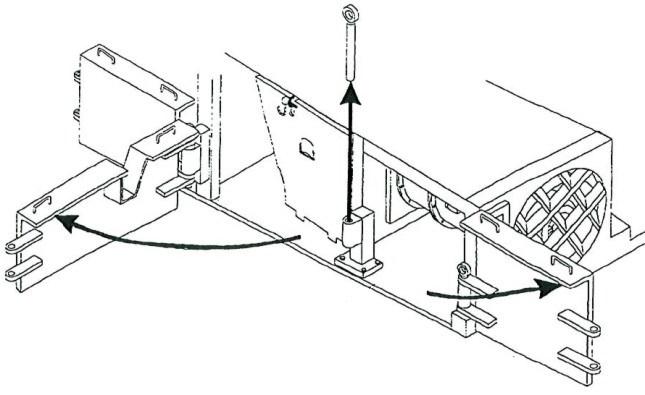
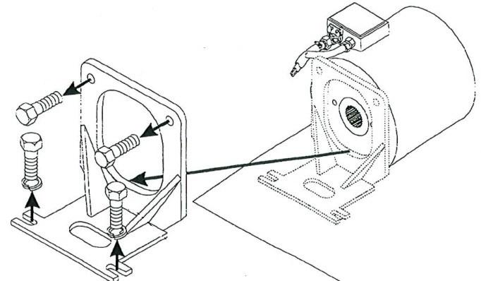
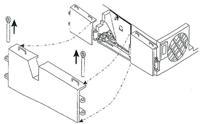
Fig. 150: Chain tension adjustment - grease take-up
Take-up rod Shims
Grease fitting Grease take-up valve