6 minute read
Tram track ....................................................................5


Tram track adjustment
Advertisement
1. Lower the conveyor tail section until it is level with the floor.
2. Raise the gathering head and cutter head and block both assemblies following standard blocking procedures.
WARNING! You could be seriously injured or killed by falling loads. Observe the safe working load limits of all blocking devices.
3. Lower the gathering head and cutter head onto the blocking so that the front end of the miner lifts off the floor.
4. Extend the stabilizer completely so that the rear end of the miner lifts off the floor.
5. Securely block under the machine. The machine must be securely supported off the ground with the tram track free to turn.
WARNING! You could be seriously injured or killed by falling loads. Observe the safe working load of all blocking devices.
6. Raise the stabilizer, gathering head, and cutter head assemblies so that the weight of the miner rests on the blocking.
7. Disconnect the trailing cable to de-energize the miner. Follow all Federal and mine lockout/tagout regulations.
WARNING! Follow all Federal and mine lockout/tagout regulations and procedures. Failure to do so could result in machine damage or serious injury or death to personnel.
8. Double check the tractor frame support blocking now that the weight of the tractor frame is completely upon it.
9. Evaluate the tram track for proper tension (Fig. 140). The tram track is at the proper tension when it hangs approximately 4 –5” (100 to 125 mm) from the bottom wear shoes when the tractor frame is blocked off the floor. Using this evaluation, determine whether step 13, 14, or 15 provides the appropriate subprocedure to correct improper track tension.
Fig. 140: Tram track adjustment
Bottom of tractor wear shoe 4 – 5” (100 to 125 mm) gap Top of tram track
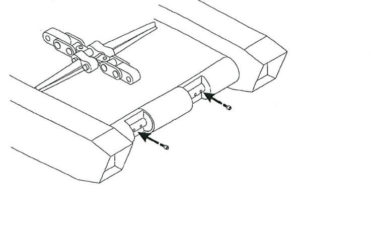
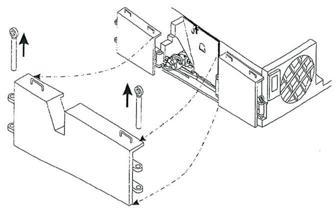
10. Remove the hex head capscrews and lock washers that secure the front rub rail to the tractor frame (Fig. 141) and open the front rub rail cover.
Fig. 141: Rub rail removal
Capscrew and lock washer
Capscrew and lock washer
Tram rub rail
11. Remove the cover plate to allow access to the idler assembly.
12. Locate the front idler take-up jack grease fitting and attach the grease gun to the fitting.
13. If the tram track tension is too tight, readjust the idler position using the following steps:
■ Pump grease into the take-up jack to extend the cylinder and remove pusher plate pressure on the idler shims.
■ Remove one or more idler adjustment shims from the idler slide channel.
■ Open the pressure release valve for the front idler take-up jack and allow the jack to contract. The pusher plate will slide backwards until it is stopped by the remaining idler shims.
■ Pump grease into the idler take-up jack to extend the cylinder, move the idler assembly forward and tighten the tram track until it is at the correct tension. The tram track is at the proper tension when it hangs 4 – 5” (100 to 125 mm) from the bottom wear shoes when the tractor frame is blocked off the floor.
14. If the tram track is too loose, readjust the idler position using the following steps:
■ Pump grease into the idler take-up jack to extend the cylinder, move the idler assembly forward and tighten the tram track until it is at the correct location. The tram track is at the proper tension when it hangs 4 – 5” (100 to 125 mm) from the bottom wear shoes when the tractor frame is blocked off the floor.
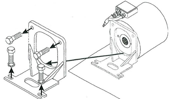
■ Insert shims (Fig. 142) into the idler slide channel until the space between the tractor frame and the pusher plate is filled.
■ Open the pressure release valve for the front idler take-up jack and allow the cylinder to contract. The idler adjustment shims will keep the idler stationary and the track tensioned.
■ Evaluate the resulting track tension and repeat these steps until the track reaches proper tension.
CAUTION! Shims must be inserted completely into the idler slide channel. A shim that is not correctly seated on the idler slide channel’s inside surface provides uneven support that can cause idler slant. A slanted idler can cause uneven wear and stress on the tram track and can cause improper operation of or damage to the tram system.
IMPORTANT! Check that the shims are correctly seated on the idler slide channel’s inside surface by looking at the channel’s inside surface from the opposite side of the miner through the space between the gathering head and the idler assembly.
Fig. 142: Tram track adjustment
Pressure relief valve Take-up cylinder Spacer Plate (can be turned 180°) Pusher plate
Shims
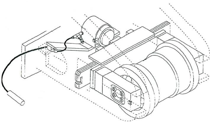
Idler assembly
15. If the tram track tension is still too loose when the entire 5” shim set is inserted into the idler slide channel, re-adjust the idler position after removing a tram track link using the following steps:
The spacer plate can be turned 180° (Fig. 142). This will allow for approximately 3 more inches of adjustment.
Pump grease into the take-up jack to extend the cylinder and remove the pusher plate pressure on the idler shims.
Remove all of the idler adjustment shims from the idler slide channel.
Open the pressure release valve for the front idler take-up jack and allow the cylinder to contract.
The tram track tension should now be reduced and separation of the tram track will be easier.
Locate a tram track link near the tram idler.
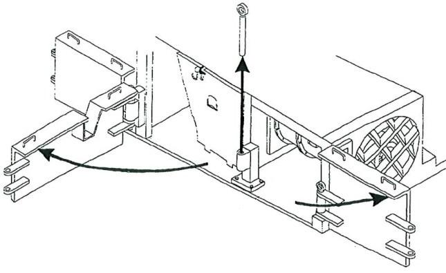
Using the hammer and punch, remove the four roll pins of the two tram track pins (Fig. 143) that secure the tram track link to the track.
Using the hammer and punch, remove the tram track pins to disconnect the link from the track. Remove the disconnected link.
Store the tram track link, one of the tram track pins and two of the roll pins in a safe place.
Connect the two ends of the tram track and using the hammer and punch, secure the two end links together with the remaining tram track pin. Using the hammer and punch, secure the tram track pin between the two links with the remaining two roll pins.
Pump grease into the idler take-up jack to extend the cylinder, move the idler assembly forward and tighten the tram track until it is at the correct tension. The tram track is at the proper tension when it hangs approximately 4 – 5” (100 to 125 mm) from the bottom wear shoes when the tractor frame is blocked off the floor.
Insert shims into the idler slide channel until the space between the tractor frame and the pusher plate is filled.
Open the pressure release valve for the front idler take-up jack and allow the cylinder to contract. The idler adjustment shims will keep the idler stationary and the track tensioned.
The idler adjustment shims will keep the idler stationary and the track tensioned.
Evaluate the resulting track tension and repeat until the track reaches proper tension.
Fig. 143: Tram track adjustment
Pad Track retention pin
Lock pin
15. When the tram track has been adjusted to the proper tension, remove the grease gun from the idler take-up jack grease fitting.
16. Open the pressure release in order to take pressure off of the take-up cylinder.
17. Close the front rub rail cover and secure the front rub rail to the tractor frame with hex head capscrews and lock washers.
18. Connect the trailing cable to energize the miner.
19. Raise the tractor frame off the blocking by lowering the stabilizer and gathering head and cutter head assemblies.
20. Carefully remove the support blocking from under the tractor frame.
21. Lower the tractor frame onto the floor by raising the stabilizer and gathering head and cutter head assemblies.
22. Carefully remove the blocking from underneath the raised stabilizer, gathering head, and cutter head assemblies.