27 minute read
Electrical system ................................................................ 5


BI016912-04 (EN-US)
Advertisement
Continuous Miner electrical system overview
Electrical energy is used to power the Continuous Miner. The electrical system is assembled for 950 3-phase AC voltages, at 60 Hertz (Hz) to match local mine power supplied via a trailing cable. Mine electrical power, stepped down by transformers, fed through circuit breakers and set up through electrical control circuitry, provides energy for the watercooled drive motors.
Basic principles
An electrical circuit provides a means of changing electrical energy into some other form of energy. An electrical circuit may cause electrical energy to change into mechanical energy, as in the case of an electrical motor, or into heat or light, as in the case of a light bulb. Just as the components in a hydraulic circuit control the flow of hydraulic fluid, many electrical components are used in an electrical circuit to direct or limit the flow of electrical energy so it can be utilized to do a particular job on the miner. Other components in an electrical circuit are protective devices to avoid damage to equipment and injuries to personnel.
Permissibility
The CM210 Continuous Miner for use in the United States is designed and built to be MSHA (Mine Safety and Health Administration) permissible: that is, the electrical system uses MSHA certified explosion proof enclosures and MSHA approved intrinsically safe circuits. All of the electrical circuit components are located within explosion proof enclosures except - the radio remote control, the radio receiving antenna, the manual tram control switches, the low oil level float switch, and the methane monitor.
A permissible explosion proof enclosure will prevent an explosion inside the enclosure from causing ignition of a methane-air atmosphere or a coal dust layer outside the enclosure. The electrical circuit components not located within an explosion proof enclosure are intrinsically safe circuits.
An intrinsically safe circuit (ISC) is incapable of producing a spark or thermal effect, under the approval criteria, which would cause an ignition of a methane-air atmosphere or a coal dust layer.
Insuring the miner is permissible and safe is the most important maintenance job. Operating equipment must be maintained by a “Qualified Person” as defined in Part 75, Title 30, of the Federal Code of Regulations.
Schematics
A schematic diagram is an illustration which shows the electrical relationship of the components and the circuits typically with standard electrical symbols (Fig. 79). A schematic diagram does not show the physical location of the components. In an electrical schematic, components are shown in their deenergized position. A set of normally open contacts (N.O.) close when the coil is energized and a set of normally closed (N.C.) open when the coil is energized. ________________________________________________________________ 5.108 CM210 Continuous Miner
Electrical
Fig. 79: Standard electrical symbols
Related components share the same designation and when tracing a particular circuit, it may be helpful to think of the flow of electricity as being similar to the flow of water through a hose. When a set of contacts are open, the current cannot flow across them, and when contacts are closed, the current can flow. When three (3) lines are connected in a tee, the current will flow in whatever direction that it can. Like water or hydraulic fluid, an electrical current will also tend to follow the path of least resistance through a circuit. Finally, for a circuit to work, the electrical current must make a complete loop, similar to hydraulic fluid going through a circuit and returning to a tank.
BI016912-04 (EN-US)
Fig. 80: Electrical component locator
Left cutter motor Right cutter motor
Left conveyor motor
Tram transformer
Hydraulic tank float switch
Left tram motor
Pump motor
Scrubber (fan) motor
Antenna
Left machine stop Right conveyor motor
Conveyor junction box
Right tram motor
Main circuit breaker enclosure
Main control case
Case machine stop
Text display
Electrical
Fig. 81: Electrical component layout
1. Left cutter motor 2. Right cutter motor 3. Left CLA motor 4. Right CLA motor 5. Pump motor 6. Left tram motor 7. Right tram motor 8. Emergency stop 9. Methane monitor display 10. Methane warning light 11. Circuit breaker reset 12. Main controller 13. I.S. tram switch
BI016912-04 (EN-US)
Fig. 81: Electrical component layout (cont.)
A. Headlights B. Area light C. Graphics display D. Scrubber motor E. Antenna F. Text display G. Fire spray H. Dust spray
Electrical
Trailing cable
A trailing cable (Fig. 78) with three power conductors, labeled L1, L2, L3, two (2) ground conductors (G), and a ground check conductor (GC) supplies power to the machine. A three-conductor 2/0 to 4/0 cable is used with the 950V machines.
Cables are designed with a fire-proof, tough outer jacket to withstand the constant abuse of flexing, reeling, and the exposure to sharp objects on the mine floor. They are not designed to withstand being run over by mobile equipment, especially Continuous Miners. Trailing cables exposed to moving equipment are required to be hung on the trailing cable hanger (Fig. 82) to prevent damage to insulation.
IMPORTANT! Hang trailing cables to prevent damage from moving equipment! Fig. 82: Trailing cable
WARNING! Never run over an unprotected trailing cable. Damaged cables should be repaired immediately.
Trailing cable hanger
Trailing cable hanger Trailing cable
The trailing cable may have breaks in its insulation. These defects in the insulation could cause exposure to high electrical currents. Never handle an energized trailing cable without the properly rated personal protective equipment (electrically insulated gloves and shoes or boots). Never let the energized trailing cable come in contact with unprotected (uninsulated) parts of your body.
DANGER! Never handle energized trailing cable without proper protective equipment. Contact with an energized trailing cable with compromised insulation could result in death by electrocution.
Trailing cables on reels can present a hazard. The reels keep the trailing cable under tension at all times. Starting and stopping of the equipment causes a tension change on the trailing cable causing the cable to move or flex constantly. The closer to the machine, the more noticeable the movement. Anyone standing near or crossing over the trailing cable could be tripped or struck by the trailing cable as it flexes.
WARNING! Always use caution when standing near or crossing trailing cables. The trailing cable may move as the machine moves.
BI016912-04 (EN-US)
Trailing cable temporary splices
Trailing cables may only be repaired under certain conditions and following specific guidelines which are outlined in MSHA 30 CFR Part 75, Subpart G (Trailing Cables).
General
electrical circuits: remote control
The incoming 950V power supply is connected to the machine via the cable handler and the incoming main circuit breaker. AC power is then transferred to the main case where it is distributed via contactors to the pump, fan, cutter, and CLA motors. Power to the DC tram motors comes from the drives. A tram transformer reduces the incoming power to 270V for the drives. The control system operates at 110V AC and consists of the control transformer, the radio control unit, the graphic display, 110V control solenoids, and various power supplies and barriers. In addition to the control system, a methane and water monitoring system is installed as an additional safety system. The machine is controlled by the radio remote of the emergency tram pendant.
The machine breakers must be in the ON position before operating in remote control mode. The power center breaker can be tripped from the remote control to provide an emergency shutdown of the machine. The power center must be reset.
Controller case
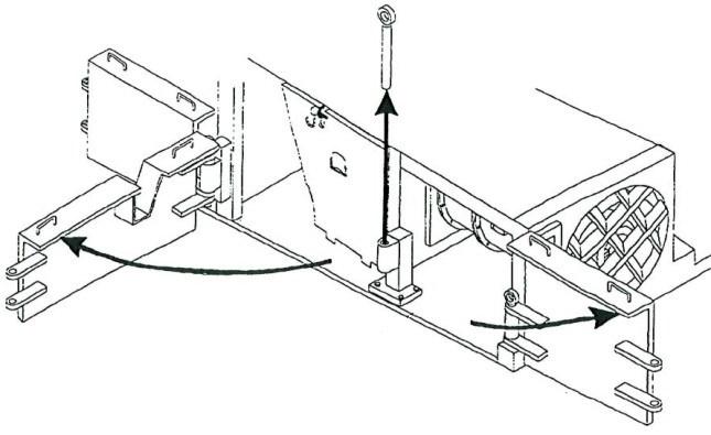
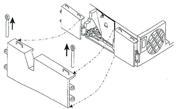
The controller case (Fig. 83) is located on the right rear side of the machine and houses the major electrical components of the miner. The control circuit breakers and the tram/fan circuit breaker can be reset from the front of the controller case. There is a machine stop button located on the front of the controller case along with a mode of operation switch.
The electrical components are mounted inside the controller on the top, bottom, front, rear, right, and left walls and on the front and rear side of the swing panel.
Fig. 83: Controller case
Controller case assembly
Electrical
fuses
ammeters
volt meters
hour meter (s)
circuit breaker
vacuum contactors
low oil warning
machine stop/e-stop Other electrical circuit components
Located in the controller assembly, fuses and control breakers protect the miner’s control circuits from over loads and short circuits. Two fuses are normally used in each circuit (primary control, secondary control, headlight, and methane monitor circuit).
The ammeters display the current being drawn by each cutter motor and conveyor motors.
The voltmeter, located in the controller assembly is wired across two legs of the 120 VAC line.
The hour meters, located in the controller assembly, are wired in parallel with the cutter motors circuit and the conveyor motors circuit to record the total amount of time that the motors are energized.
Mounted inside the operator’s case, the circuit breaker provides maximum protection for the electrical components on the miner in the event of short circuits and extreme overload conditions. The magnetic type breaker has 400 or 600 amperes continuous rating.
A circuit breaker is a device for interrupting current flow in a circuit under normal or abnormal conditions. Under normal continuous current rating, a circuit breaker is a single switching device. When the current is above the normal rating, either on overload or short circuit current, the circuit breaker is an automatic overcurrent protective device. The function of the circuit breaker corresponds basically to that of a switch in combination with a fuse. A circuit breaker will automatically interrupt current flow when the conditions are abnormal without damage to itself. The circuit breaker mechanism is set to interrupt the current at a particular overload value and it can interrupt a short circuit current.
The vacuum contactor will close when the 120 VAC energizes the coil. The contactor opens when the coil or 120 VAC is de-energized.
IMPORTANT! If the low oil warning light comes on when the circuit breaker is closed. Be sure to fill the reservoir before starting the motors.
This circuit is controlled by a float switch assembly located in the hydraulic tank. The level one switch is normally open and when the oil level gets low, the switch closes and completes a circuit across the low oil warning light.
The machine stop/emergency stop switch is located on the left side of the miner, opposite the operator’s area. The contacts in the emergency stop switch are normally closed. Depressing the large mushroom push button causes the moving contact to be pushed away from the stationary contact, breaking the control circuit and de-energizing all the coils wired in the main control circuit. The de-energized coils open all their contacts, shutting down the miner except for the headlights. Once the button is released, power is again available up to the control circuit.
BI016912-04 (EN-US)
electric motor
electrical tram case
main controller case
Squirrel-cage type induction motors are used on miners. The operation of the motors depends on a rotating magnetic field created by current flow in the stator windings. As the field rotates around the stator, voltages are induced in the rotor conductors, causing currents to flow. These currents create magnetic fields that cause a repelling force between the rotor and the stator causing the rotor to turn.
To describe the rotating field action of a typical motor, as the current changes in value and direction, the field rotates clockwise around the stator. Lines of magnetic force cut across the conductors in the rotor. The magnetic lines pass through the air gap between the rotor and the stator at right angles to the face of the rotor inducing voltages in the rotor conductors which causes large alternating currents to flow. Since a current carrying conductor in a magnetic field has force exerted on it that tends to move at right angles to the magnetic field, torque is exerted on the rotor periphery. Stator currents are identical in magnitude and lag their respective voltages by the same angle. They are spaced electrically 120 degrees apart.
The tram case is located on the right side of the machine inside of the crawler frame. It is an explosion proof enclosure, which houses the electrical traction components: the tram transformer, two DC drives, the tram breaker , junction block for the right side conveyor motor and cutter motor and the tram interface for radio and manual. To adjust the tram interface, see cutter motor feedback adjustment.
The main controller case is located on the left side of the machine, midway the tractor frame inside the crawler frame. It is an explosion proof enclosure, which houses many of the electrical components.
Inside the enclosure is a hinged swing out panel. Mounted on the front side of the panel are the PLC unit, battery back-up power supply, fuses, and terminal strips.
Mounted on the back side of the swing out panel are the conveyor forward and reverse contactors, instantaneous overloads, conveyor motor thermal overloads, scrubber contactor, scrubber motor thermal overload, timer which is in the conveyor forward circuit, and the e-stop relay.
Mounted on the rear wall of the enclosure are the cutter motor contactors (A and B) , pump motor contactor, the delay between cutter contactors A & B, pump motor thermal overload, cutter motor instantaneous overloads, cutter motor thermal overloads and terminal boards.
Located on the floor, left side is a connection point for the left traction motor. The connection block is provided so if there is a need to change the left traction motor leads, it can be done without passing a cable through the frame of the machine. Also on the floor on the left side is a low oil level relay assembly.
Electrical
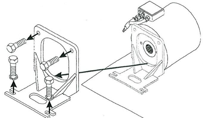
operator’s controller case The operator’s case is located on the right side of the machine near the rear bumper or in the operator’s compartment. It is an explosion proof case.
Mounted inside the case is the main circuit breaker/auxiliary circuit breaker, control transformer, methane monitor relay, methane bridge varistor, electrical metering package, control fuses and breakers, headlight switch, lighting relay and O.E. relay, and radio/manual switches. Also located inside the auxiliary controller are the manual start/stop switches as well as bridge rectifiers and scrubber water solenoid.
The trailing cable enters into this enclosure at the bottom left corner, facing the case. The panic bar for the right side of the machine is mounted to the enclosure and operates the pump stop switch to shut the machine down. On the front bottom of the case are breaker levers. The lever to the left operates the main circuit breaker, the lever in the center operates the auxiliary breaker.
Explosive methane gas is one of the greatest hazards in the mines. Because methane is colorless and odorless, a person cannot easily detect its presence. For this reason, the miners offer a methane monitor to “sniff out” methane in the air. When energized, the methane monitor maintains a continuous check on methane gas concentration. A typical readout has LED indicators that display the percentage of methane gas in larger numerals.
Consult the manufacturer’s manual and literature in the parts book for your machine for the setup, operation, and maintenance of the methane monitoring system.
methane monitor
BI016912-04 (EN-US)
motor mate “MMG”
motor mate “MMH”
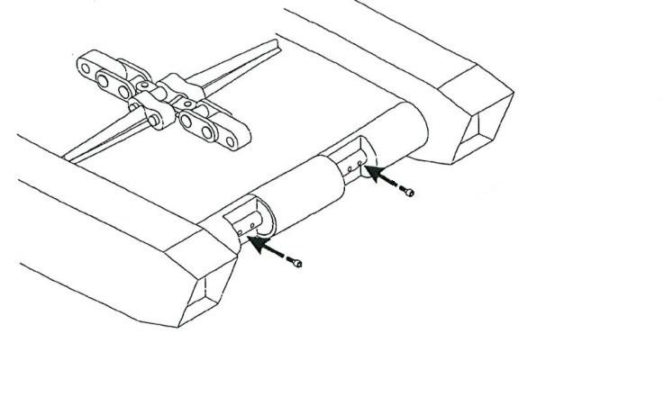
Fig. 84: Traction case Traction case
The traction case (Fig. 84) is accessed by opening the controller cover and then opening the swing panel. Typically mounted on the rear wall are motor mates and a terminal block.
IMPORTANT! This component location information is typical. Always verify component layout with the information in the parts book for your machine.
Each motor mate is triple output inductive current transducer. It takes the current from each leg of the motor and reduces it to a 4 to 20mA output that is sent to the control system.
Motor mate “MMG” is the current transducer for the left drive motor.
Motor mate “MMH” is the current transducer for the right drive motor.
Motor Mate “MMH” Terminal block Motor Mate “MMG”
Electrical
control breaker “CB4”
control breaker “CB5”
Control breaker “CB6”
control breaker “CB7”
control breaker “CB8”
control breaker “CB9”
control breaker “CB10”
control breaker “CB11”
control breaker “CB12”
control breaker “CB13”
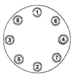
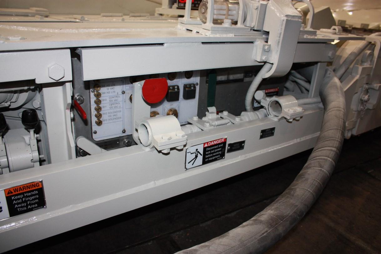
Fig. 85: Controller case Controller case—control breakers
Mounted on the front wall of the controller case (Fig. 85) are control breakers.
“CB4” is a 15A breaker for the 120VAC- supply voltage.
“CB5” is a 15A breaker for the 120VAC+ supply voltage.
“CB6” is a 10A breaker for the 120VAC- side of the area light circuit.
“CB7” is a 10A breaker for the 12V0AC+ side of the area light circuit.
“CB8” is a 20A breaker for the 12VAC- side of the head light circuit.
“CB9” is a 20A breaker for the 120VAC+ side of the head light circuit.
“CB10” is a 5A spare breaker.
“CB11” is a 5A breaker on the 120VAC side of the machine controller power supply circuit.
“CB12” is a 5A breaker on the 120VAC- side of the solenoid circuit.
“CB13” is a 5A breaker on the 120VAC+ side of the solenoid circuit.
BI016912-04 (EN-US)
radio/manual mode
radio remote control
machine controller, power suppy, and module tram case
radio system battery
System overview: radio remote control
The miner is radio remote controlled. Manual operation is not allowed for production operation unless the miner has an operator’s pit and canopy. Manual operation is for troubleshooting and maintenance, and must be operated under roof support.
The operating controls are available either in radio remote control or in manual control. The control mode is selected by using three switches: SW1, SW2, and the Light Switch.
Switch SW1 sections 1-2 and 5-6 selects 120v power to be connected to either the manual push buttons or to the machine controller. Section 7-8 of SW1 connects +24v power from the machine controller power supply when in “radio”. SW1 removes manual control from the tram interface when radio control is selected.
SW2 connects motor control to the manual push buttons and isolates control from the controller. In the radio position, SW2 isolates the push buttons and connects motor control to the controller.
The Light Switch has three positions: manual, off, and radio. In the radio position, the miner operator can turn the head lights on and off from the radio remote by controlling the HR relay.
The radio remote control system consists of a battery powered portable transmitter, which, sends UHF radio signals to the miner. The encoded control signals, from the remote, are decoded by the machine controller unit located in the main controller case. The remote has a built-in antenna while the controller, located in the explosion proof main controller, has a external antenna.
The machine controller responds to the control signals from the remote and activates the machine functions. The machine controller power supply provides 110 VDC for the solenoids to control the hydraulic valves and 24 VDC for the radio display, and traction module. The traction module provides tram direction and speed radio signals to the tram interface. Controller outputs also control the 120 VAC machine circuits.
An optional battery back-up to the power supply will provide power to operate the fire suppression solenoid and the breaker on and off.
The radio remote has a rechargeable battery, which has a recharge socket for connection to the out-by battery charger. The complete remote unit is changed out each shift. The remote panel has switches or “keys” for all of the miner functions.
The complete system includes a battery charger which is used to recharge the remote battery. This unit is usually located above ground. Four remote units can be recharged at the same time. A built-in radio controller and screen will allow the remote to be tested before use underground and to change channels on the remote.
The machine controller power supply has an optional battery back-up which provides control power to operate the controller and solenoids for fire suppression, breaker on and off and to reset the power supply and tram breaker. The battery back-up, in conjunction with a hydraulic accumulator, will allow control of those functions from the remote in the event of a power outage.
The radio system has a diagnostic display on the miner in an explosion proof enclosure, which, can be seen at the right rear of the miner. Refer to the separate radio manual that came with your machine for complete use of the diagnostic display.
The machine stop/e-stop bypass circuit allows the operator, when using radio remote control, to bypass the machine stop/emergency stop palm switch located on the left side of the miner for about 30 seconds. This is useful in cases where the miner has become jammed against a rib causing the normally closed machine stop/e-stop switch to be stuck open. The ESB relay contacts bypass the emergency stop push button.
The manual start push button for the scrubber fan motor contactor, E, does not have a holding circuit. Therefore, when in manual control the fan motor and the scrubber spray will only operate as long as the push button is held. There is no manual stop push button.
For miners with an operator’s pit and canopy, there is a holding circuit for the scrubber fan motor contactor. The fan motor stops, after a short time delay, when the cutter motors are stopped.
The tram “deadman” switch, also called the foot switch, is a handoperated push button located at the operator’s control panel for miners without an operator’s pit. If there is an operator’s pit, the tram “deadman” is a foot operated control switch which must be held closed.
Electrical
battery back-up
radio system diagnostics
machine stop/e-stop bypass
scrubber fan
tram dead man (optional)
BI016912-04 (EN-US)
cutter motor feedback
The miner operator has control over the tram speed when the cutter motors are not running. The Continuous Miners have a feedback circuit from the cutter motors to the tram motors so that when the cutter motors are running the maximum forward tram speed is determined by the load on the cutter motors. This is accomplished by monitoring the phase current for one of the cutter motors and feeding this current level to the tram control circuit. The amount of phase current on a cutter motor is a measure of the load on the motor.
Electrical
Power circuit with control
Electric power is supplied to the control transformer and is available to the methane monitor and to all contactors after the trailing cable is connected, the circuit breakers CB1 and CB2 are turned on, and when CB2 contacts close in the control circuit.
The schematic shown in Fig. 86 is typical of a power schematic. Always refer to the schematic in your parts book for your machine.
Fig. 86: Power circuit with control
BI016912-04 (EN-US)
Methane monitor circuit
The methane monitor detects methane gas when the continuous miner is powered up. Before any motor or function occurs, the methane monitor checks for methane gas. If the methane monitor shows zero methane, the methane monitor relay will close. When the methane monitor relay closes, it supplies power to the area lights including the head light if the light switch is on. The methane monitor is powered from the control transformer. The low oil system will also have control power.
The schematic shown in Fig. 87 is a typical methane monitor circuit. Always refer to the schematic in your parts book for your machine.
Fig. 87: Methane monitor circuit
Electrical
Control headlights and area lights circuit
The light switch has three positions: manual, off & radio. When the power is turned on to the continuous miner, the methane monitor relay is closed and the light switch is off. When the light switch is turned to the manual position, the headlights and the area lights will come on. When the light switch is turned to the radio position, the headlights only (not the area lights) can be turned on and off with the radio. The schematic shown is typical of a headlight switch schematic. Always refer to the schematic in the parts manual for this machine. Caution should always be taken!
The headlights can be turned off and on from the remote console at any time that the system is remote position and the remote console is on by:
The schematic shown in Fig. 88 is a typical lighting circuit. Always refer to the schematic in your parts book for your machine.
Fig. 88: Control headlights and area lights circuit
BI016912-04 (EN-US)
Low oil circuit
The low oil circuit indicates when the oil is low in the hydraulic oil tank. The float switch energizes the LOR (low oil relay) and turns on the LOL (low oil light) in the case that the oil level becomes too low. The low oil switch is not located within an explosion proof enclosure. It is part of an intrinsically safe circuit. A permissible ISC (intrinsically safe circuit) is incapable of producing a spark or a thermal effect.
The schematic shown in Fig. 89 is a typical low oil circuit. Always refer to the schematic in your parts book for your machine.
Fig. 89: Low oil circuit
TO 120 VAC CONTROL SYSTEM
Electrical
Pump motor power circuit with control
The pump motor can be started in manual by depressing the momentary switch. This completes the circuit across coil “F” and starts the pump motor. There are three thermal overloads in the pump circuit: OL11 is the thermal overload for the pump and OL12 and OL13 are the thermal overloads for the tram. This will supply three (3) phase power to the tram transformer and to the electrical tram drives. For the control circuit, when the pump contactor energizes, the “F” interlock closes. When the three (3) phase power is on the tram drives, the control contacts in the tram drives close and will complete the holding circuit for the pump motor. To stop the pump motor, depress the momentary pump stop switch. The pump motor has to be running before any other motor can be started.
The schematic shown in Fig. 90 is a typical pump motor power circuit. Always refer to the schematic in your parts book for your machine.
BI016912-04 (EN-US)
Fig. 90: Pump motor circuit with control
Electrical
Cutter motor power circuit with control
The pump motor must be running before the cutter motors will start. To start the cutter motors, the “SHIFT” key is pressed and held and then the “CUTTER ON” key is pressed. This completes the circuit across coil “A” and starts the left cutter motor, as well as starting the Time Delay 2, “TD2”, timer for the “B” contactor right cutter motor. Both cutter motors do not start at the same time. When the timer times out, the circuit across coil “B” is completed and the right cutter motor will start. The holding circuit interlock “A” and “B” must be closed. There are motor mates and thermistors on both motors that provide feedback to the control system on the operating state of the motors. In the event that an operating parameter exceeds a preset value, the operating system can shutdown the motors. To manually stop the cutter motors, depress “CUTTER STOP” switch.
The schematic shown in Fig. 79 is a typical cutter motor power circuit. Always refer to the schematic in your parts book for your machine.
Fig. 79: Cutter motor circuit
BI016912-04 (EN-US)
Fig. 91: Cutter motor power circuit
Electrical
Conveyor motor circuit with control
The pump motor must be running before the conveyor motors will start. The conveyor motors can be started in manual by depressing the momentary switch. This completes the circuit across coil conveyor forward (CF) and will start both conveyor motors. There are four (4) overloads in the conveyor circuit. There are two (2) thermal overloads and two (2) instantaneous overloads; one (1) for each motor OL5, 6, 7 and 8 for the control circuit when the conveyor contactor comes in the “CF” interlock closes. This completes the holding circuit. To stop the conveyor motor, depress the momentary conveyor stop switch.
The schematic shown in Fig. 92 is a typical conveyor motor circuit. Always refer to the schematic in your parts book for your machine.
Fig. 92: Conveyor forward and reverse motor circuits with control
TO POWER TRANSFORMER
BI016912-04 (EN-US)
Fig. 93: Scrubber motor circuit with Scrubber motor circuit with control
The pump motor must be running before the scrubber motor will start. The scrubber motor can be started in manual by depressing the momentary switch. This completes the circuit across coil “E” and starts the scrubber motor. This energizes the screen sprays for the scrubber. There is one (1) overload in the scrubber circuit called the OL10 thermal overload. The scrubber does not have a holding circuit.
The schematic shown in Fig. 93 is a typical scrubber motor circuit. Always refer to the schematic in your parts book for your machine.
Electrical
Fire suppression in radio remote
The control system uses a solenoid output to drive the fire suppression system on the continuous miner. the fire suppression can be activated at any time from the remote control console. If the machine is fitted with the battery backup version of the power supply, the fire suppression can also be activated in battery standby mode. The system will remain in battery standby mode for at least ten minutes after loss of main power to the machine.
The schematic shown in Fig. 94 is a fire suppression circuit in radio remote. Always refer to the schematic in your parts book for your machine.
Fig. 94: Fire suppression in radio remote schematic
BI016912-04 (EN-US)
Shear up/down in radio remote
The shear up solenoid is energized and moves the cutter boom up. When the shear down solenoid is energized, the cutter boom is lowered. Pressing and holding the radio remote key keeps the shear up and shear down solenoid energized. The pump motor must be running in order to raise or lower the cutter boom.
The schematic shown in Fig. 95 is a typical shear up/down in radio remote circuit. Always refer to the schematic in your parts book for your machine.
Fig. 95: Shear up/down schematic
Electrical
Stabilizer cylinder raise/lower in radio remote
The pump motor must be running in order to raise or lower the stabilizer cylinder.
The schematic shown in Fig. 96 is a typical stabilizer cylinder raise/ lower in radio remote circuit. Always refer to the schematic in your parts book for your machine.
Fig. 96: Stabilizer cylinder raise/lower schematic
BI016912-04 (EN-US)
Gathering pan raise/float in radio remote
The pump motor must be running in order to raise or lower the gathering pan.
The schematic shown in Fig. 97 is a typical gathering pan raise/float in radio remote circuit. Always refer to the schematic in your parts book for your machine.
Fig. 97: Gathering pan raise/float schematic
Electrical
Conveyor left/right in radio remote
The pump motor must be running in order to control the conveyor raise, lower, and swing left/right.
The schematic shown in Fig. 98 is a typical conveyor left/right in radio remote circuit. Always refer to the schematic in your parts book for your machine.
Fig. 98: Conveyor left/right raise lower in radio remote schematic
BI016912-04 (EN-US)
Cutter dust sprays in radio remote
The cutter dust sprays are typically turned on automatically when the cutter motors are started. The control system has the possibility to turn the cutter water sprays on and off from a key on the remote console. However, this function is normally not available due to the wiring configuration of most miner electrical systems. If remote control of the water sprays is required, contact your local representative or mine personnel.
The schematic shown in Fig. 99 is a typical cutter dust sprays in radio remote circuit. Always refer to the schematic in your parts book for your machine.
Fig. 99: Cutter dust sprays in radio remote schematic
Electrical
Breaker on and off in radio remote
The control system allows the main circuit breaker CB1, CB2, or auxiliary and tram breaker to be turned on, off, and to reset a tripped breaker using the radio remote control console. This normally requires that a battery backup version of the power supply to be installed on the machine.
The schematic shown in Fig. 100 is a typical breaker on/off in radio remote circuit. Always refer to the schematic in your parts book for your machine.
Fig. 100: Breaker on/off in radio remote schematic
BI016912-04 (EN-US)
Tramming
The miner can be trammed manually or via the remote console. Before the tram motors will start, the pump motor must be running.The following tramming configurations are enforced by the control system for safety reasons:
■ Spilt track tramming is limited to SPEED 1.
■ Single track tramming is normally limited to SPEED 1.
■ It is possible to speed up a single track from SPEED 1 to SPEED 2 providing that tramming is started in SPEED 1.
■ Tramming is limited to SPEED 1 while the cutters are on.
■ While the cutters are running, reverse speed can be incremented even while the forward tram keys are being pressed.
The schematic shown in Fig. 101 is a typical tram circuit. Always refer to the schematic in your parts book for your machine.