7 minute read
Machine control system........................................................5


BI016912-04 (EN-US)
Advertisement
machine controller
power supply
input/output modules Machine control system
A multi-component system is used to control and monitor the functions of the machine. This system consists of the following main components:
■ Machine controller
■ Power supply
■ Input/Output (I/O) modules
■ Radio remote
■ Graphics display
The following information is presented as a general guide to the capabilities and functions of the control system. Before attempting to operate, service, or troubleshoot the continuous miner, training must be completed.
The machine controller is the main control unit of the system. It includes the radio data receiver which is used to receive and decode commands from the radio remote.
The control system has its own power supply, with the option of having battery backup for the power supply, which provides power to the machine controller and I/O modules.
Input/Output modules are used to read data from and/or send commands to the following machine functions:
■ Cutter motors (left and right)
■ Gathering head motors (left and right)
■ Traction motors (left and right)
■ Pump motor
■ Hydraulic oil level
■ Methane monitoring
Based on the parameter settings and the input received from different components, the control systems has the ability to issue error messages, fault messages, and/or shutdown the machine.
radio remote
The radio remote (Fig. 16) is a battery powered remote used to control the continuous miner during normal operations.
WARNING! Radio remote control systems are dangerous. The continuous miner operator cannot operate a remote system until he is properly trained in the operation of the system. Remote control systems sometimes have automatic features of which untrained operators and workers may not be aware.
Fig. 16 Radio remote (typical)
The radio remote shown may vary from the radio remote that shipped with your machine.
IMPORTANT! Refer to the radio remote control operation manual supplied with your machine for information regarding the operation of your specific remote control.
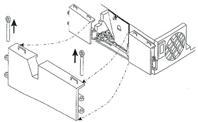
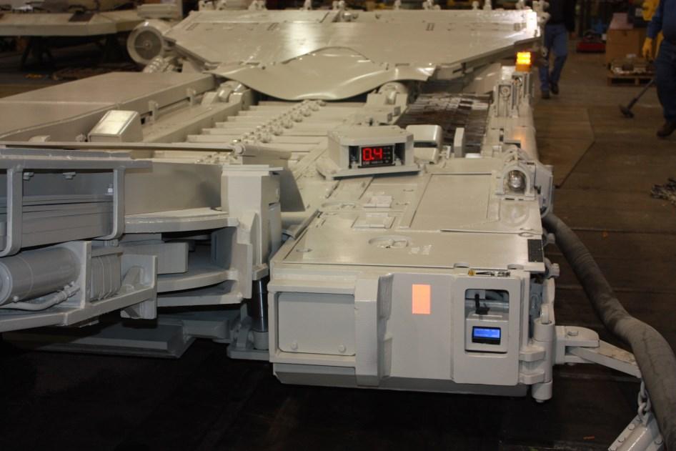
There are two displays located on the machine: a graphics display located at the operator’s case and a text display located near the back right hand side of the machine (Fig. 17). Both screens are used to display diagnostic information on the miner.
Fig. 17: Control system display locations (typical)
Graphics display
Text display
displays The graphics display, located on the operator’s case, is used to monitor machine operating parameters, for diagnosing error and fault codes, and for input of operating parameters.
The text display, located on the near the back right hand side of the machine, has the same functions as the graphics display. If the control system loses power, the text display will remain powered through the battery back up.
NOTICE! Information priority is given to the graphics display unless the graphics display becomes unhealthy. The two monitors will not necessarily display the same information at the same time.
There are different screens that can be displayed: production monitoring, function monitoring, diagnostic, motor hours, and fault pages. A system halt message can appear as a pop-up dialog box in the middle of any screen. A message will appear when a critical conditions has occurred that prevents continued operation of the machine in a safe manner. The message box cannot be cleared and it is necessary to recycle power to the control system to restore machine operation.
Normal display pages
The main diagnostic screen (Fig. 18) is displayed during normal remote control operation of the machine. The screen presents real time diagnostic and performance information.
Fig. 18: Main page, example
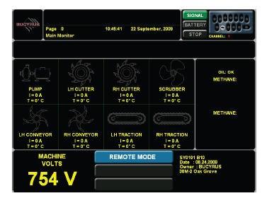
Graphics display
Text display
BI016912-04 (EN-US)
System Menu
The control system provides information, diagnostic, and setup screens that are grouped together in the system menu (Fig. 19). The system menu is accessed by using either display module and a remote control handset.
To access and navigate the system menu using the radio remote:
Press the SHIFT and MENU key to access the system menu screen.
IMPORTANT! All functions and motors are shut down and disable when the system menu is selected.
Press CONV UP or CONV DOWN to move the cursor up and down the list.
Press SHIFT and MENU to select the highlighted item
To leave the menu and return to remote mode, press SHIFT and
REMOTE.
Fig. 19: System menu, example
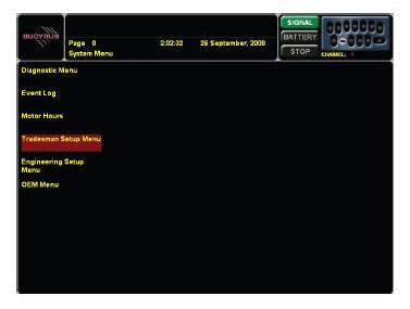
Graphics display
Fig. 19: System menu, example, continued
Text display
BI016912-04 (EN-US)
Diagnostic Mode
Diagnostic mode allows a large number of monitoring screens to be selected and displayed while the machine is operating. Each screen provides helpful troubleshooting information such as machine information, software revision, and machine configuration. It also provides the status of the motors, digital and analog inputs, etc. Diagnostic mode is for informational purposes only. No configuration changes can be made within this mode.
To navigate through the screens, hold the SHIFT switch while pressing a conveyor switch. To return to the main menu, press SHIFT and MENU
Graphics diagnostics includes the following pages:
■ Main monitor ■ Production monitor ■ Pump monitor ■ Cutter monitor ■ Conveyor monitor ■ I/O monitor - relay outputs ■ I/O monitor - digital inputs ■ I/O monitor - analog outputs ■ Solenoid modules ■ Thermistor monitor ■ Motor mate network monitor
See Fig. 20 for example screen shots of various diagnostic pages.
Fig. 20: Graphics display diagnostic pages, examples


BI016912-04 (EN-US)
Fig. 20: Graphics display diagnostic pages, examples, continued

Text diagnostics includes the following pages:
■ Main monitor ■ Machine information ■ Pump diagnostics ■ Cutter diagnostics ■ Conveyor diagnostics ■ Fan diagnostics ■ Tram diagnostics ■ 24VDC digital input ■ I/O monitor - relay board ■ I/O monitor - solenoid board ■ I/O monitor - analog outputs ■ Solenoid board diagnostics ■ Relay board status ■ Power supply status ■ Thermistor module status
Fig. 21: Text display diagnostic pages, examples
BI016912-04 (EN-US)
Fault log
The fault log (Fig. 22) allows the user to view the last 100 faults that have occurred since the log was last cleared.
To navigate the fault log page:
Press the CONV UP or CONV DOWN key to move the cursor up or down the page.
Press SHIFT and CONV UP or CONV DOWN move up or down one page.
It is possible to clear the fault log under the Engineering Setup Menu, which is password protected.
IMPORTANT! It is not recommended that the fault log be cleared unless the machine controller has been replaced. Retaining the faults is very helpful in troubleshooting a problem when a controller is sent for service. Faults cannot be retrieved once they have been cleared. Use caution and only clear the log if it is absolutely necessary.
Once a fault has been selected, the SHIFT and MENU keys can be used to access more information on the fault (Fig. 23).
Fig 22: Fault log, example

Graphics display
Fig. 22: Fault log, examples, continued
Text display
Once a fault has been selected, the SHIFT and MENU keys can be used to access more information on the fault (Fig. 20).
Fig. 23: Fault detailed information, example
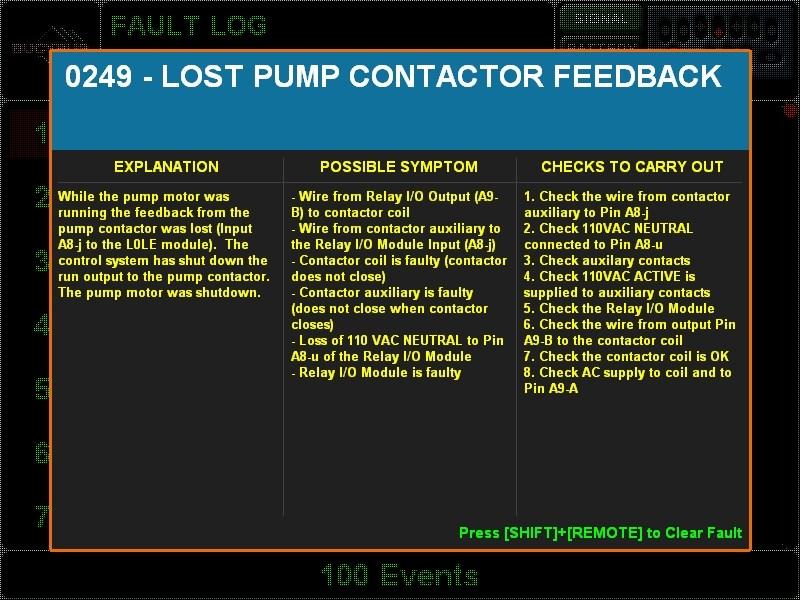
For a complete list of faults, see the troubleshooting section of this chapter.
BI016912-04 (EN-US)
Hour meters
Selecting hour meters (Fig. 24) from the Main Menu will display runtime for the following motors: pump, fan, left cutter, right cutter, and conveyor. Time is displayed in hours:minutes:seconds format. This runtime only reflects accumulated time since the controller has been installed or since the counter was last reset. The hour meters can be cleared under the Engineering Setup Menu, which is password protected.
IMPORTANT! The hours meters should only be cleared when a motor is replaced or when the machine controller is installed. To keep an accurate log of a motor’s total hours, the information should be recorded anytime data is cleared.
Fig. 24: Hour meters, examples

Tram pendant The machine can be operated using a pendant control (Fig. 25) connected to the miner by an umbilical cable. This control is used in the event that the operator loses radio link with the mine to safely recover the miner from the face to an area under supported roof for troubleshooting and maintenance.
The pendant controller allows limited operation of the machine: tramming and pump motor activation to provide hydraulic power to raise or lower the cutting head.
In order to use the pendant, it must be connected to the machine via a pigtail. After plugging in the umbilical cord, the “MACHINE” mode of operation switch must be rotated to the “E-TRAM”.