8 minute read
Mechanical assemblies...................................................... 5


Mechanical assemblies
Mechanical assemblies
Advertisement
The following pages contain a brief description of the major mechanical assemblies that are on the Continuous Miner.
WARNING! This section is intended to familiarize the user with the major mechanical assemblies of the Continuous Miner. All mechanical maintenance should be performed by a qualified technician with the knowledge of the function of the assemblies involved.
Cutter head
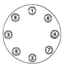
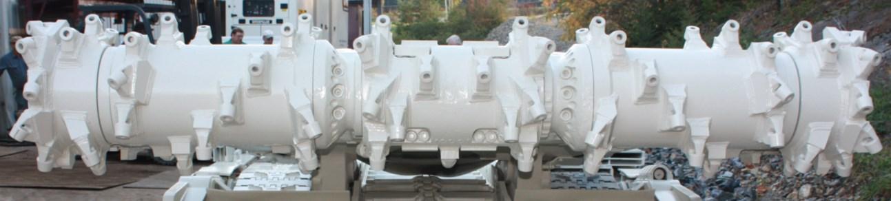
The Continuous Miner has a rotary, drum type cutter head with bit blocks arranged spirally on a set of cylindrical drums (Fig. 41) that direct the cut material to the center of the gathering head mechanism. The cutter head has a heavy-duty gear-drive cutting system. The fixeddrum cutter head hinges directly to the machine chassis at its own pivot point at the back of the cutter boom frame. There are no cutting chains on the cutter head assemblies.
With the bits installed, the cutter head has a cutting diameter that varies per specification. The width of the cutter head and cutter motor horse power varies per model specification. The AC electric motors are mounted on each side of the cutter head support frame. A torque shaft through the center of the motor drives an input gear case that is mounted to the support frame. From the input gear case, a shaft is gear driven to the cutter head gear case in the drum. This main gear case on each side of center is driven by the cutter head shaft and removes material from the face to provide clearance for the cutter head gear case on that side of the miner.
Cutting power is transferred through a series of bevel gears. A torque shaft from the clutch (through the center of the motor) drives an input gear case that is mounted to the support frame. This input gear case is removable from the final drive gear case. Different drum rotation speeds are available by changing gear sets in the input gear case.
The operator controls the height of the cutter head by controlling two double-acting cylinders through hydraulic control valves. Cutter head height reach and speed of cutter head rotation varies per model specification (See Technical Data Chapter 6 for specifications).
Fig. 41: Cutter head
BI016912-04 (EN-US)
Carbide bits and bit blocks
The carbide-tipped cutter bits are mounted into holders called bit blocks (Fig. 42). While a variety of bit and bit block designs are available to meet light, tough, or average mining conditions, all are designed to absorb vibration to maintain cutter efficiency. The conical bits also rotate as they cut to produce a self-sharpening effect. The bits and blocks may be deployed around the drum in different bit lacing patterns to give the best performance under different conditions.
IMPORTANT! Inspection of the bits and bit blocks before the start of each shift will reduce later problems. Mining with dull, bent or broken bit blocks increases dust and noise levels, as well as putting excessive strain on both cutter and tram drives.
Fig. 42: Cutter bit and bit blocks
Bit block Cutter bit

Conveyor chain
The miner is equipped with a conveyor chain assembly that runs through the center of the miner and transports the mined material from the gathering head to the rear of the miner for haulage at a high loading rate compatible with the miner’s cutting output. The conveyor chain (Fig. 43) is made up of one basic chain assembly which repeats sequentially along the entire chain loop (see Maintenance section in this chapter for Conveyor chain maintenance).
Fig. 43: Conveyor chain
Conveyor chain
Mechanical assemblies
Conveyor tail section
The conveyor tail section (Fig. 44) pivots and has the ability to be raised and/or lowered. The conveyor pivots on the main frame behind and just below the cutter head pivot. Two single acting hydraulic cylinders permit the operator to raise the conveyor discharge end to a maximum height and clearance varying per machine or to lower the discharge end of the conveyor to a specific ground clearance.
A double-acting hydraulic cylinder on the right side of the conveyor permits the discharge end to swing 45 degrees left or right of the conveyor centerline. The range in height and swing of the conveyor with an overhang permits the conveyor to accommodate any haulage vehicle.
Two AC electric motors drive through the gathering head gear cases to a foot shaft sprocket to propel the conveyor chain.
Fig. 44: Conveyor tail section

Conveyor tail section
Gathering head and Continuous loading arms (CLAs)
The gathering head (Fig. 45) loads the material that is mined by the cutter head assembly onto the conveyor for transport to the rear of the machine. The gathering head assembly consists of a gathering pan and two continuous loading arms (CLAs), each driven by a bevel gear case (or pot). Each CLA has 3 to 6 fingers, or blade fan-type rotating assemblies. The CLA’s are driven by rotary drive shafts in their respective gear cases. The CLA’s gather and force the cut material into the conveyor throat and onto the moving flights.
The AC motors that drive both the conveyor and the gathering head are located on each end of the gathering head assembly. Through each motor lies a specially-constructed torque shaft that extends across the rear of the gathering head frame into a heavy duty input gear case on that side driving the bevel gear input shaft to it.
The input gear cases contain bevel and helical gears that drive each main gear case (pot). These in turn drive the CLAs and the foot shaft at the base of the conveyor. The foot shaft extends across the gathering pan from the right gear case to the left gear case and has a sturdy 4 or 5 tooth sprocket at its center to drive the conveyor chain.
BI016912-04 (EN-US)
The left gear case drives the left CLA and the right gear case drives the right CLA. Together, they both drive the foot shaft.
The gathering head pivot is below and in front of the cutter head pivot. Two hydraulic cylinders raise and lower the gathering head in response to the controls.
Fig. 45: Gathering head and continuous loading arms (CLA’s)
Gathering head pivot (located behind cover)

Gathering head cylinder (2) (located behind cover)
Conveyor CLA (2) Main gearcase pot (located under the CLA)
Footshaft
Mechanical assemblies
Traction system
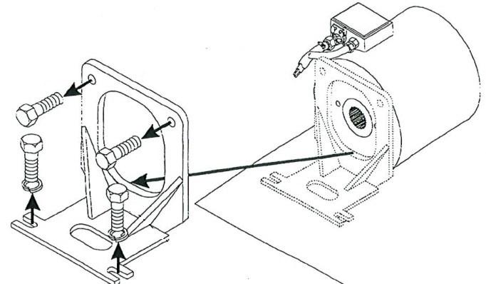
The Continuous Miner is trammed by two individually controlled traction systems (Fig. 46). Each traction assembly has an electric motor connected to a tram drive gear case. The gear case encloses a bevel gear that drives a planetary gear. The gear case reduces the rotation speed, increases torque, and provides a right-angle drive to the drive sprocket. The drive sprocket is directly connected to a tram drive planetary gear case. This gear case reduces the rotation speed, increases torque, and drives the track belt. (See the Maintenance section in this chapter for track belt adjustment procedures and Traction assembly maintenance procedures.)
There are three (3) tram speeds: 1st, 2nd, and 3rd. The speeds are selected from the radio remote.
Fig. 46: Traction system
tractor frame/chassis tractor (main frame)
Traction case
Track belt
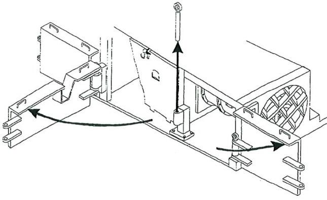
The tractor frame (Fig. 47) is a rectangular structure of high-strength steel weldments that supports major operating assemblies such as the cutter head frame, gathering head frame, conveyor and traction units. It houses supporting assemblies, the crawler and take-up mechanisms and planetary gear cases. It anchors the pivots for the conveyor, the gathering head, and the cutter head frame. The clevises for the hydraulic cylinders actuating these assemblies are also on the main/tractor frame. The frame also provides a platform for electrical and hydraulic control modules, all water controls and plumbing and the optional operator’s control compartment. Integral within the frame is the hydraulic reservoir or oil tank.
Fig. 47: Main frame/tractor frame
Rear bumper plate
Stabilizer shoe cylinder clevis
Electrical case
Oil tank Scrubber components
Cutter head pivot
Cutter head cylinder clevis
Gathering head cylinder clevis Crawler idler guides
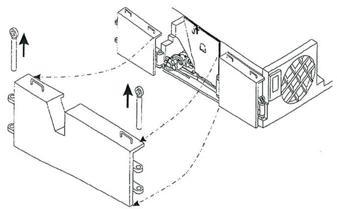
stabilizer shoe A stabilizer shoe (Fig. 48), located beneath and at the rear of the tractor frame, may be lowered to anchor the back end of the machine and provides a greater downward thrust of the cutter head for hard-cutting while preventing backward creep of the miner. The stabilizer shoe is raised and lowered hydraulically by a double acting cylinder that moves the shoe bracket up or down.
Fig. 48: Stabilizer shoe
Stabilizer shoe

Mechanical assemblies
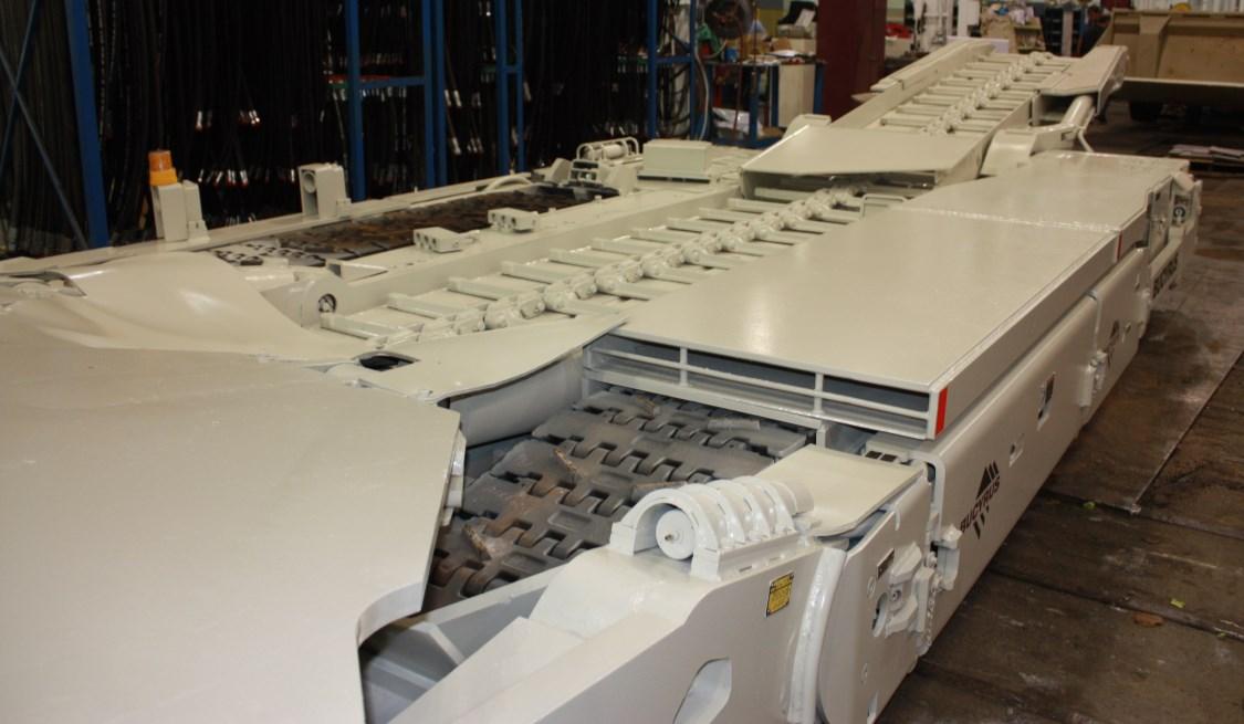
Fig. 49: Conveyor assembly Conveyor assembly
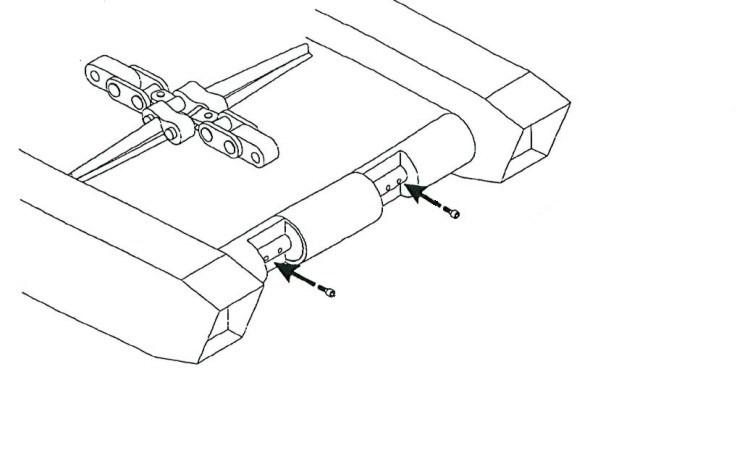
The conveyor assembly (Fig. 49) is attached to the main chassis at right and left hand independent pivot points. The conveyor is articulated vertically around these pivot points to assist in optimum loading into a haulage vehicle. Independent pivots allow removal of the conveyor assembly without disturbing the cutting head or gathering head components.
The conveyor assembly includes the following:
■ An intermediate conveyor structure that includes the right and left hand pivot points for attaching to the main chassis, upper mounting clevises for the two conveyor raise cylinders, and a horizontal pivot arrangement at the rear for mounting the rear conveyor subassembly. ■ A rear conveyor subassembly that includes: – a mating horizontal pivot arrangement allowing sideward swinging movement up to 45° on either side of the machine center line to assist in optimum loading into a haulage vehicle, and – a tail roller shaft for the conveyor chain and two hydraulic cylinders to maintain proper tension in the chain when the geometry of the conveyor assembly changes during the operation.
The intermediate and discharge conveyor structures each include a special noise dampening running deck for the conveyor chain and a throat clearance designed for optimum loading rates (see the general arrangement drawing for you machine for dimensions).
Rear conveyor section
Conveyor pivot pin Intermediate conveyor section Chassis pivot points