
5 minute read
CARBURETOR INSPECTION AND REPAIR

from Briggs & Stratton Vanguard Twin Cylinder OHV Liquid-Cooled Engines Repair Manual - PDF DOWNLOAD

VanguardTM Twin-Cylinder OHV Liquid-Cooled Engine Section 4 - Engine Overhaul
6. Compress springs with needle nose pliers and insert spring behind brushes.
Fig. 117
7. Install brush retainer plate. 8. Assemble rubber seal to starter housing, Fig. 118. a. Be sure notch in rubber seal is inserted over tab on housing.
BRUSH RETAINER
NOTCH TAB
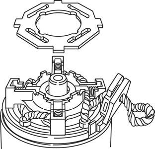
Fig. 118
9. Install end cap, Fig. 119. a. Torque through bolts to 70 in. lbs. (8.0 Nm). 10. Install solenoid.

Fig. 119
Disassemble Carburetor
1. Remove fuel shut off solenoid with washer. 2. Remove carburetor lower body screws and lift lower body straight away from upper body, Fig. 120. a. Discard gasket.

Fig. 120
VanguardTM Twin-Cylinder OHV Liquid-Cooled Engine Section 4 - Engine Overhaul
3. Remove fixed main jets .
NOTE: Carburetor is equipped with a different size fixed main jet for each cylinder, Fig. 121. The carburetor is marked “L” (#1 cylinder) and “R” (#2 cylinder).
4. Remove pilot jets .
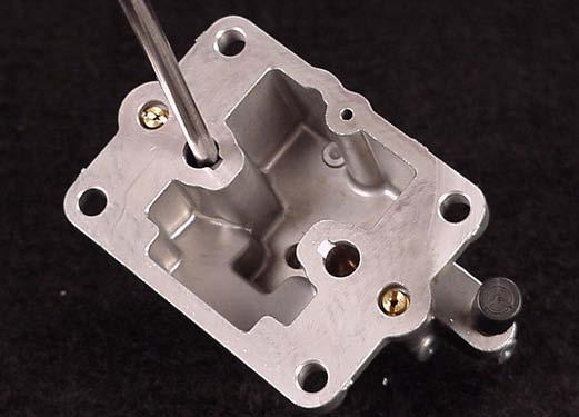
Fig. 121
5. Remove float and inlet valve, Fig. 122.
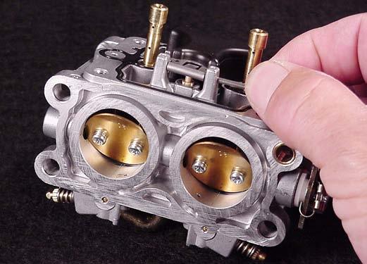
Fig. 122
If idle mixture screws are equipped with adjustment limiter caps, use a pliers to remove them before removing idle mixture screws. 6. Remove idle mixture screws and springs, Fig. 123.
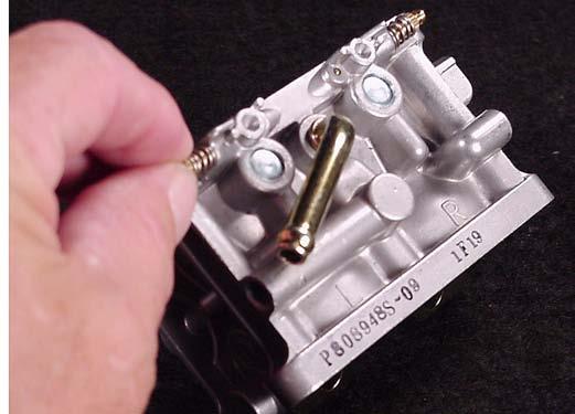
Fig. 123
7. Remove welch plugs, Fig. 124.
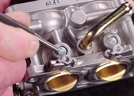
Fig. 124
8. Mark throttle plates before removing so that they may be re-installed in the same position. Top and bottom edges are beveled.
VanguardTM Twin-Cylinder OHV Liquid-Cooled Engine Section 4 - Engine Overhaul
9. Remove throttle shaft, spacer and seal, Fig. 125.
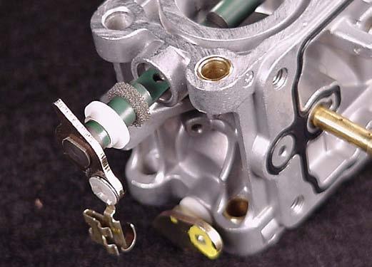
Fig. 125
10. Mark choke plate so it may be returned to its original position. 11. Remove choke shaft and nylon bushings, Fig. 126.

Fig. 126
This completes the carburetor disassembly procedure.
Carburetor Cleaning Recommendations
CAUTION: Wear suitable skin protection when using cleaners and follow instructions on container. 1. Disassemble carburetor. 2. Remove and discard all old gaskets, seals and sealing material. 3. Use commercial carburetor cleaning solvents (such as Briggs & Stratton Spray Cleaner, Part
#100041 or 100042) to clean carburetor parts and body. 4. When cleaning non-metallic parts (plastic, nylon,
MinlonE, etc.), do not leave in commercial carburetor cleaner more than 15 minutes.
CAUTION: To prevent eye injury, always wear eye protection when using compressed air.
5. Use only compressed air (blowing in both directions) to clean out all openings and passages.
Check Throttle, Choke Shaft And Body For Wear
1. Lay carburetor on a flat surface and check throttle and choke shaft clearance as shown, Fig. 127. Throttle shaft and choke shaft clearance must not exceed .010” (.25 mm).
CAUTION: Parts containing rubber, such as seals, O-rings, inlet needles, seats or pump diaphragms should never be placed in commercial carburetor cleaner. Do not use wires, drills or any other devices to clean out metering holes or passages.

Fig. 127
VanguardTM Twin-Cylinder OHV Liquid-Cooled Engine Section 4 - Engine Overhaul
2. Inspect throttle shaft and choke shaft for wear,
Fig. 128. Make sure bushing hole is circular and there is no wear. Replace if worn.
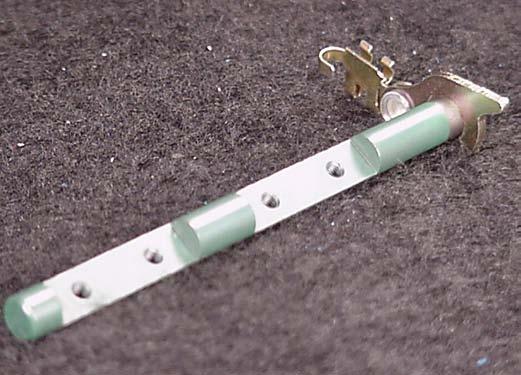
Fig. 128
Assemble Carburetor
When assembling carburetor, use new seals and gaskets. 1. Install new welch plugs with a 5/16” (8 mm) punch, Fig. 129. 2. Use a sealant such as Permatex® #2 or nail polish on outside diameter of plug to prevent air leaks.

Fig. 129
3. Install new throttle shaft seal , Fig. 130. 4. Install throttle shaft with spacer . IMPORTANT: Install one throttle plate at a time. Check throttle shaft for freedom of operation before installing other throttle plate.
NOTE: Use LOCTITE) 222® on screw threads and torque to 6 in. lbs. (0.7 Nm).

Fig. 130
5. Install choke shaft with new bushings, Fig. 131. a. Lever must face up. b. Install choke plate. Check for binding.
NOTE: Use LOCTITE) 222® on screw threads and torque to 6 in. lbs. (0.7 Nm).

Fig. 131
VanguardTM Twin-Cylinder OHV Liquid-Cooled Engine Section 4 - Engine Overhaul
6. Install idle mixture screws and springs. DO NOT tighten screws at this time, Fig. 132. DO NOT install limiter caps at this time.
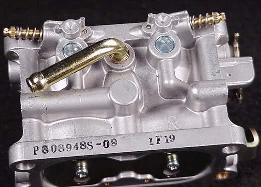
Fig. 132
7. Install main jets and pilot jets, Fig 133. “L” or #1 cylinder is equipped with #114 main jet . “R” or #2 cylinder is equipped with #118 main jet . Both pilot jets are #48.

Fig. 133
8. Assemble inlet valve to float and install float assembly, Fig. 134.
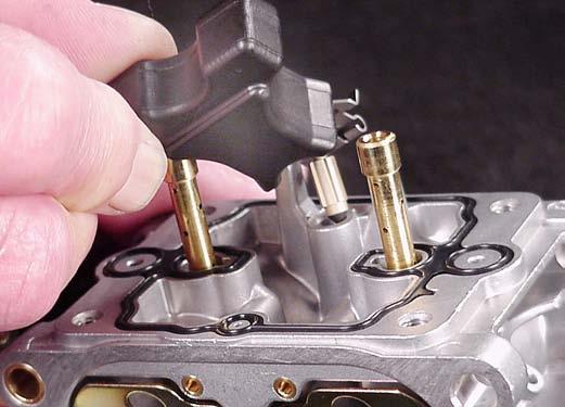
Fig. 134
9. Install lower body gasket. Make sure gasket does not twist or kink. 10. Assemble lower body. Make sure gasket remains in position, Fig. 135. Tighten screws to 22 in. lbs. (2.5 Nm).

Fig. 135
11. Install fuel shut off solenoid with washer. a. Torque to 90 in. lbs. (10.0 Nm).
VanguardTM Twin-Cylinder OHV Liquid-Cooled Engine Section 4 - Engine Overhaul


