1 minute read
PISTON AND CONNECTING ROD

from Briggs & Stratton Vanguard Twin Cylinder OHV Liquid-Cooled Engines Repair Manual - PDF DOWNLOAD

VanguardTM Twin-Cylinder OHV Liquid-Cooled Engine Section 5 - Engine Assembly
INSTALL PISTON AND CONNECTING ROD
NOTE: Install #1 piston and connecting rod first.
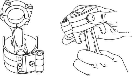
1. Oil piston rings, piston skirt, and compress rings with ring compressor Tool #19070. a. Place piston and ring compressor upside down on bench with projections on compressor facing up, Fig. 140. b. Tighten ring compressor evenly until rings are fully compressed. c. Then loosen ring compressor very slightly so that compressor can be rotated on piston skirt while holding connecting rod.
250-144
Fig. 140
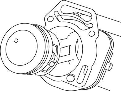
2. Lubricate cylinder bores and crankpin and rotate crankshaft until it as at bottom of stroke 3. Install #1 piston with notch or offset casting mark on piston toward flywheel side, Fig. 141. a. Push piston down by hand until connecting rod is seated on crankpin.
NOTCH OR CASTING MARK TOWARD FLYWHEEL SIDE FLYWHEEL SIDE “OUT 1” CYLINDER #1 “OUT 2” CYLINDER #2
PTO SIDE
Fig. 141
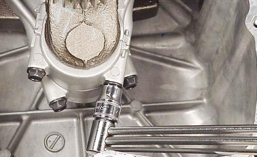
4. Assemble connecting rod cap to rod with match marks aligned , Fig. 142. a. Torque screws to 125 in. lbs. (14.0 Nm). 5. Rotate crankshaft two revolutions to check for binding. Rod should also be free to move sideways on crankpin. Repeat for #2 cylinder. CAUTION: The words “OUT-1” on #1 connecting rod and “OUT-2” on #2 connecting rod must be facing PTO side. Failure to use a torque wrench can result in loose connecting rod screws causing breakage or tight connecting rod screws causing scoring.