4 minute read
REPLACING PINION GEAR ASSEMBLY

from Briggs & Stratton Vanguard Twin Cylinder OHV Liquid-Cooled Engines Repair Manual - PDF DOWNLOAD

VanguardTM Twin-Cylinder OHV Liquid-Cooled Engine Section 4 - Engine Overhaul
4. Engage flats on plunger with fork in drive lever and assemble solenoid to starter, Fig. 102. a. Torque nuts to 70 in. lbs. (8.0 Nm). 5. Install field coil wire and nut. a. Torque nut to 90 in. lbs. (10.0 Nm).
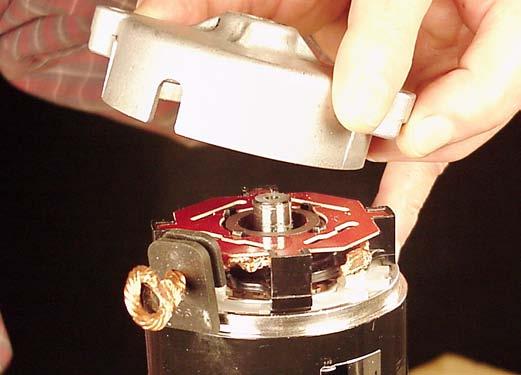
Fig. 102
Pinion gear replacement requires complete starter motor disassembly. It is recommended that a complete inspection of all components be performed at that time.
Disassemble Starter
For ease of disassembly and assembly, clamp drive end housing in a vise as shown, Fig. 103.
1. Remove solenoid. 2. Remove starter thru bolts. 3. Remove brush end cap, Fig. 103.
NOTE: To prevent losing brush springs, do not remove brush retainer until starter housing has been removed from drive end cap, Fig. 103.
CAUTION: Take care not to damage drive housing or mounting surface.
Fig. 103
4. Remove starter housing from drive end cap.
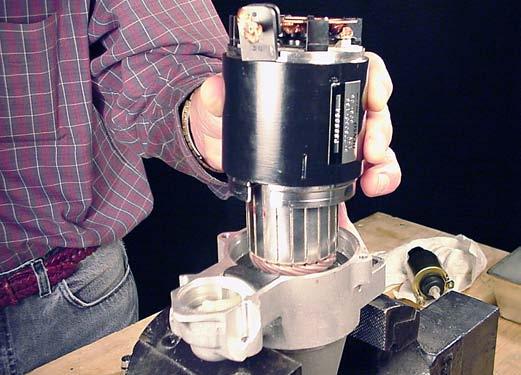
Fig. 104
VanguardTM Twin-Cylinder OHV Liquid-Cooled Engine Section 4 - Engine Overhaul
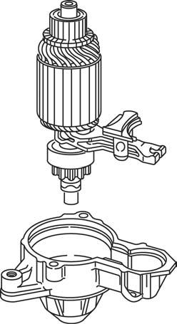
5. Remove armature and pinion gear with drive lever from drive end cap, Fig. 105.
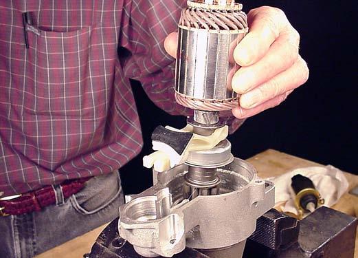
Fig. 105
6. Remove spacer from armature shaft. 7. Use a 14 mm deep socket and drive retainer from C-ring, Fig. 106. 8. Remove and discard C-ring and retainer. Always use a new C-ring and retainer.
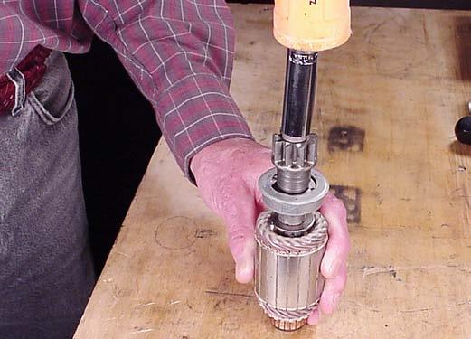
Fig. 106
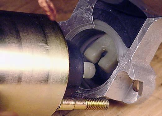
9. Remove pinion gear and clutch assembly, Fig. 107.
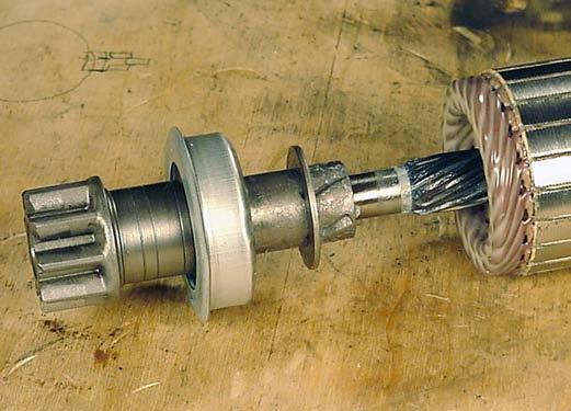
Fig. 107
Clean and inspect helix. If helix is damaged, replace starter. Inspect bearing journals on armature shaft for wear or damage. If bearing journals are worn or damaged, replace starter.
NOTE: Bearings in drive and brush end cap are not replaceable.
Inspect Armature Commutator
The armature commutator may be cleaned with fine sandpaper (#300 - 500 grit). DO NOT use emery cloth. Commutator may be machined to no less than 1.062” (27.0 mm), Fig 108. Slots between commutator bars should be cleaned with a hack saw blade after cleaning or machining. The armature should be checked for shorts with a growler.
1.062” (27.0MM)
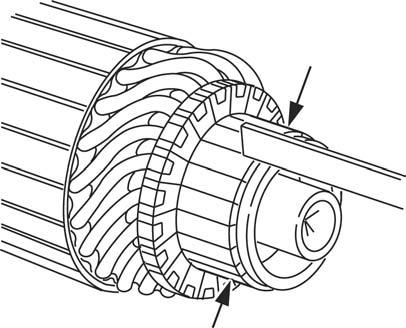
Fig. 108
VanguardTM Twin-Cylinder OHV Liquid-Cooled Engine Section 4 - Engine Overhaul
Inspect Brushes
Minimum brush dimension is 1/4” (6.0 mm). If brushes are worn less than specification, replace the starter housing, Fig. 109.
1/4” (6.0MM)
Fig. 109
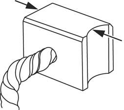
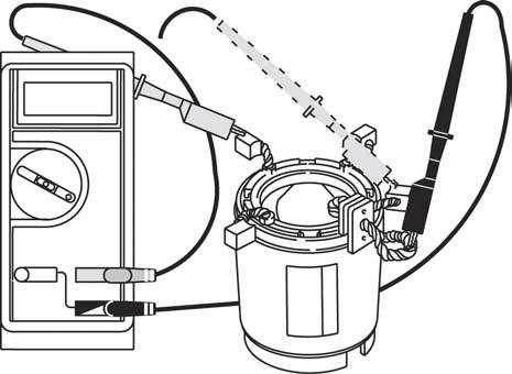
Use digital multimeter and check for continuity between field coil wire and brushes shown, Fig. 110. The following test will be made with the meter in the (Diode Test) Position. 1. Attach either meter test lead to field coil wire. 2. Contact first one, then other brush with other test lead as shown. a. Meter should make continuous tone (continuity). b. If meter does not make a tone, (no continuity) replace starter housing.
Fig. 110
FIELD COIL WIRE 3. Attach either test lead to starter housing, Fig. 111. 4. Contact first one, then other brush with other test lead as shown. a. Meter should make continuous tone (continuity). b. If meter does not make a tone, (no continuity) replace starter housing.
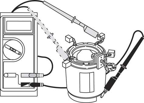
Fig. 111
Assemble Pinion Gear
1. Lubricate helix with a light coat of grease and assemble pinion gear and clutch. 2. Assemble new retainer to shaft. 3. Install new C-ring. 4. Pry up on retainer until C-ring snaps into groove in retainer, Fig. 112.
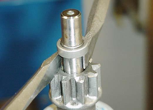
Fig. 112
5. Assemble spacer to armature shaft, Fig. 113.
VanguardTM Twin-Cylinder OHV Liquid-Cooled Engine Section 4 - Engine Overhaul
NOTE: Lip on spacer must face bearing in drive end cap.
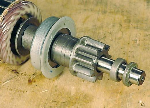
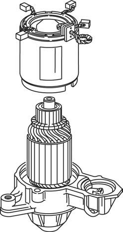
Fig. 113
Assemble Starter
1. Assemble drive lever to pinion and install armature and drive lever into drive housing, Fig. 114.
NOTCH
TAB
Fig. 115
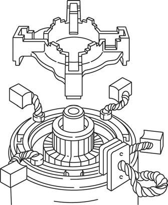
4. Install brush holder, inserting tabs on brush holder into slots in starter housing, Fig. 116.
PINION DRIVE LEVER
DRIVE HOUSING BRUSH HOLDER TABS
SLOTS BRUSH HOLDER TABS
SLOTS
Fig. 114
2. Align tab on drive lever with notch in housing, Fig. 48. 3. Assemble starter housing to drive housing, aligning notch 115.
Fig. 116
SLOTS
5. Insert brushes into brush holder, Fig. 117.


