3 minute read
INSPECTION AND REPAIR

from Briggs & Stratton Vanguard Twin Cylinder OHV Liquid-Cooled Engines Repair Manual - PDF DOWNLOAD

VanguardTM Twin-Cylinder OHV Liquid-Cooled Engine Section 4 - Engine Overhaul
CYLINDER HEAD INSPECTION AND REPAIR
Disassemble Cylinder Head
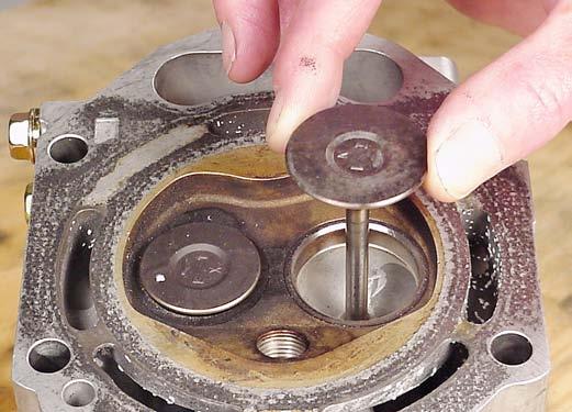
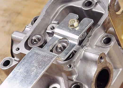
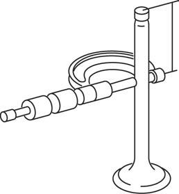
1. Place a shop rag or short section of rubber fuel line under valves inside combustion chamber to hold valve in place while compressing spring. 2. Thread rocker arm support screw into cylinder head a few turns and compress spring with valve spring compressor, Tool #19347, Fig. 80. Remove the following: a. Valve spring retainer locks b. Valve spring retainers c. Valve springs d. IN and EX valves
Fig. 80
3. Remove and discard valve stem seals, Fig. 81.
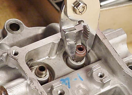
Fig. 81
Inspect And Repair
1. Check cylinder head. Be sure all gasket material is removed from surfaces before checking. Use a gasket scraper if necessary. a. Inspect cylinder head for cracks or damage. b. Use a surface plate or straight edge and check cylinder head mounting surface for distortion. If mounting surfaces are distorted more than .004” (0.1 mm), the cylinder head must be replaced, Fig. 82.
It is not recommended that cylinder head mounting surfaces be resurfaced.

Fig. 82
2. Check valve guide bushings for wear using reject gauge, Tool #19382 , Fig. 83. a. Replace valve guide if gauge enters guide 1/4” (6 mm) or more.

Fig. 83
VanguardTM Twin-Cylinder OHV Liquid-Cooled Engine Section 4 - Engine Overhaul
Remove Valve Guide
1. Press out old valve guide using bushing driver, Tool #19367 , Fig. 84.

Fig. 84
Install Valve Guide
1. Press in new valve guide using bushing driver, Tool #19416 , Fig. 85. a. Press in until tool bottoms on valve guide bushing boss. CAUTION: Do Not use a hammer to install bushing.

Fig. 85
2. Use reamer pilot guide, Tool #19345 and finish reamer, Tool #19444 and ream new valve guide, Fig. 86. a. Use Stanisol or kerosene to lubricate reamer. b. Turn reamer clockwise through entire guide. c. Keep turning reamer clockwise when removing reamer. d. Flush out all chips.
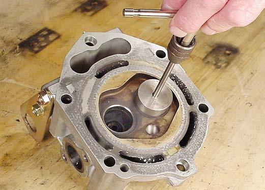
Fig. 86
Reface Valves And Seats
1. Measure valve stem diameter at specified distance from end of valve, as shown in Fig. 87.
Replace if less than .233” (5.92 mm).
1.500” (38MM)
Fig. 87
2. Valve seats may be reconditioned using valve seat cutter tool #19237 and #19343. If valve seat is wider than dimension shown in Fig. 88, a narrowing cutter should be used to ensure that contact area of valve seat is centered on face of valve as shown in Fig 89.
VanguardTM Twin-Cylinder OHV Liquid-Cooled Engine Section 4 - Engine Overhaul
a. Use a 605 cutter to narrow seat from bottom and a 155 cutter to narrow seat from top, Fig. 88.
NOTE: If valve seat is loose or cracked, replace cylinder head.
1-16”-3/64” (0.8 MM TO 1.2 MM) 45°
60° CUTTER
VALVE SEAT DIMENSIONS 15° CUTTER
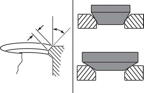
Fig. 88
3. Valve faces may be resurfaced to 45°. See Fig. 89 for dimensions for valves.
3/16”-1/16” (1.2MM-1.6MM) 1/32” MINIMUM
Fig. 89
4. Lap valves and seats with valve lapping tool, #19258 and valve lapping compound, tool #94150.
NOTE: In most instances it is more economical to replace the valves than to reface them.
Assemble Cylinder Head
1. Use valve guide driver, Tool #19416 and install new intake valve stem seals, Fig. 90. a. Oil inner surface and lip of valve stem seal. b. Press seal on to valve guide bushing until it bottoms.
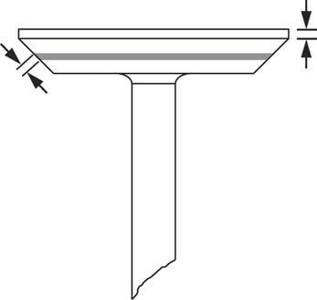
Fig. 90
2. Install valves, Fig. 91.
NOTE: Lightly coat valve stems with Valve Guide Lubricant #93963 before installing valves but be sure valve guide lubricant is NOT on valve face, seat or end of valve stem.