
4 minute read
STARTER CURRENT DRAW TEST

from Briggs & Stratton Vanguard Twin Cylinder OHV Liquid-Cooled Engines Repair Manual - PDF DOWNLOAD

VanguardTM Twin-Cylinder OHV Liquid-Cooled Engine Section 2 - Troubleshooting
NO LOAD STARTER CURRENT DRAW TEST
Remove starter motor.
To hold starter securely while testing, clamp starter mounting bracket in a vise. DO NOT clamp starter housing in a vise or field windings or magnets may be damaged.
Testing Starter (No Load)
The No Load starter current draw test will be performed with the meter in the 300mV position. The DC Shunt must be installed on the negative (-) terminal of the battery, Fig. 11.
ATTACH NEGATIVE BATTERY CABLE
Fig. 11
1. Attach RED meter test lead to RED post terminal on shunt. 2. Attach BLACK meter test lead to BLACK post terminal on shunt.
3. Attach negative battery cable to a good ground such as drive housing. 4. Attach positive battery cable to battery terminal on solenoid. 5. Attach one end of jumper wire to solenoid tab terminal, Fig. 11. 6. Activate starter by contacting positive battery terminal with other end of jumper wire , Fig. 11. a. Allow 3 seconds for meter reading to stabilize. 7. Current draw should not exceed 50 amps DC.
If amperage draw exceeds specification, replace starter. Hard Starting
Make sure the oil level is correct. This engine is equipped with a “Low Oil Pressure Sensor” and will not start if the oil level is too low. Make sure drive unit is disengaged. A loose drive belt like a loose blade can cause a backlash effect, which will counteract engine cranking effort.
NOTE: Magnetron® ignition system requires a minimum of 350 RPM before it will produce a spark.
Systematic Check
If the engine is hard starting or will not start and the cause of malfunction is not readily apparent, perform a systematic check in the following order: 1. Ignition 2. Carburetion 3. Compression This check-up, performed in a systematic manner, can usually be done in a matter of minutes. It is the quickest and surest method of determining the cause of failure.
VanguardTM Twin-Cylinder OHV Liquid-Cooled Engine Section 2 - Troubleshooting
Check Ignition (With Engine Starter)
With spark plugs installed, attach a #19368 ignition tester to each spark plug lead and ground the other end of the tester as shown in Fig.12. Activate the electric starter. If spark jumps the tester gaps, you may assume the ignition system is functioning satisfactorily.

Fig. 12
NOTE: Engines equipped with Magnetron® ignition system will still display spark at tester with a partially or fully sheared flywheel key. A partially sheared flywheel key will affect ignition timing and engine performance.
If spark does not occur look for:
1. Improperly operating interlock system 2. Shorted equipment stop switch wire 3. Two closed diodes in ground wire harness (see: Troubleshooting Ground Wire Harness) 4. Incorrect armature air gap 5. Armature failure
Check Ignition (Engine Running)
If engine runs but misses during operation, a quick check to determine if ignition is or is not at fault can be made by installing Tool #19368 tester between the spark plug lead and each spark plug, Fig.13. A spark miss will be readily apparent when the engine is running. If spark is good but engine misses, check for a fouled spark plug.

Fig. 13
Check Ignition (Fouled Plug or Other Causes)
To check for a fouled spark plug or a non-functioning cylinder, attach Tool #19368 tester between the spark plug lead and each spark plug. With engine running at top no load speed, ground one spark plug, Fig. 14. The engine should continue to run on the other cylinder. Repeat this test with the other cylinder. If the engine will not continue to run when making this test, the cylinder that is NOT grounded is not functioning and/or the spark plug is fouled. Install a new spark plug before proceeding. When replacing spark plugs always use Briggs & Stratton #491055 or #496018.
VanguardTM Twin-Cylinder OHV Liquid-Cooled Engine Section 2 - Troubleshooting
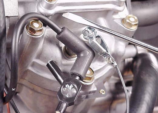

Fig. 14
If miss continues:
The problem may be carburetion or compression related. See Check Carburetion and/or Cylinder Balance Test and Cylinder Leakdown Test.
Troubleshooting Ground Wire Harness
The ground wire harness contains two diodes. If a diode fails “open,” the cylinder with the open diode will continue to run when the equipment key switch is turned off. If a diode fails “short,” the cylinder with the shorted diode will not run (no spark). Refer to Failure Diagnosis Table for symptoms.
Testing Ground Wire Harness
The Digital Multimeter, Tool #19464 is recommended to test the ground wires. The following test will be made with the meter in the “Diode Test Position”.
DIODE FAILURE DIAGNOSTIC TABLE
Ground Wire Harness
Diode Diode
Equipment Switch OFF
ON
SWITCH ON SWITCH OFF CAUSE
Engine runs on one cylinder. Engine runs. (Both Cylinders) Won’t Run (No Spark) Engine runs. (Both Cylinders) Shuts Off OK
Only one cylinder shuts Off
Engine won’t shut Off 1 Closed Diode
1 Open Diode
2 Closed Diodes
2 Open Diodes
Fig. 15
In the Diode Test position, the meter will display the forward voltage drop across the diode(s). If the voltage drop is less than 0.7 volts, the meter will “Beep” once as well as display the voltage drop. A continuous tone indicates continuity (shorted diode). An incomplete circuit (open diode) will be displayed as “OL.” 1. Insert RED test lead into receptacle in meter. 2. Insert BLACK test lead into receptacle in meter. 3. Rotate selector to (Diode Test) position. 4. Insert RED test lead into ground wire terminal (brown wire) receptacle in engine harness, Fig. 16. Leave attached for remainder of test. 5. Touch BLACK test lead probe to ground wire tab terminal on ignition coil for #2 cylinder.


