4 minute read
CYLINDER LEAKDOWN TEST

from Briggs & Stratton Vanguard Twin Cylinder OHV Liquid-Cooled Engines Repair Manual - PDF DOWNLOAD

VanguardTM Twin-Cylinder OHV Liquid-Cooled Engine Section 2 - Troubleshooting
there will be no RPM loss. When the other cylinder is grounded out the engine will stop.
NOTE: A twin cylinder engine will run well on one cylinder as long as the power required for the application does not exceed the power produced by the one cylinder.
An accurate method of checking the sealing capability of the compression components is by using the cylinder leakdown tester Tool# 19545. The leakdown test will show any variation between cylinders as well as identify which components may be at fault. A regulated amount of compressed air is used to pressurize the combustion chamber with the piston at TDC on the compression stroke. By listening for air leaks, it is possible to isolate a specific component or components causing a problem. An engine in good condition will display a reading in the green area on the outlet gauge with a minimum of audible leakage. A reading in the yellow or red area along with high audible leakage indicates a problem with the compression components. A small amount of air leakage is normal in all engines, including new engines, providing that the outlet gauge remains in the green area. However, if a single component is displaying more audible leakage, look to that component for a potential problem. For example, frequently a slight air leak at the head gasket may not register on the gauge. Obviously the head gasket would require replacement, as any leak at the head gasket would have an adverse affect on engine performance.
NOTE: When testing water cooled engines, always remove the radiator cap. If air bubbles are observed in the coolant while the combustion chamber is pressurized, this indicates that the head gasket is leaking internally and/or the cylinder head or block is cracked.
Compression Testing Using Leakdown Tester, Tool #19545
1. Run engine for 5 minutes allowing engine to reach operating temperature.
NOTE: If engine is cold or cannot be started, air flow may be higher (gauge readings lower) because compression components are not at normal operating temperatures.
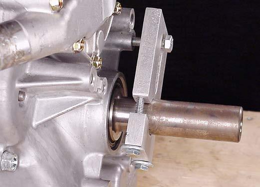
2. Remove spark plugs from engine. Disconnect air cleaner tube and crankcase breather tube at carburetor intake elbow. 3. Rotate crankshaft in direction of operation until piston for cylinder being tested is at top dead center of compression stroke. 4. Assemble the clamping tool to the crankshaft.
Torque screws to 150 in. lbs. Insert drive end of a 3/8” breaker bar into slot of clamp or install screw through slot into bolt circle hole in crankcase cover, Fig. 22.
Fig. 22
NOTE: The crankshaft must be held with the piston at top dead center to seal the combustion chamber and eliminate any chance of rotation. If the engine is installed in an application, many times the equipment can positively lock the crankshaft from moving.

VanguardTM Twin-Cylinder OHV Liquid-Cooled Engine Section 2 - Troubleshooting
5. Pull the regulator adjustment knob out and turn knob counterclockwise as far as it will go, Fig. 23. Make sure air outlet valve is closed.

Fig. 23
6. Connect the tester to the shop air source (minimum air pressure of 70 psi). 7. Install the outlet hose into the spark plug hole of the cylinder being tested. Be sure “O” Ring is seated to prevent air leak at spark plug hole.
Connect other end to tester. 8. Turn regulator adjustment knob clockwise until the tester’s needle is on the set point. Push knob in to lock. Slowly open air outlet valve and note position of needle on gauge, Fig. 24.
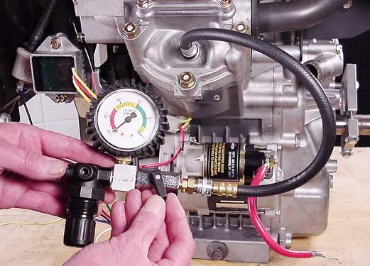
Fig. 24
NOTE: Any air leaks at the connections or fittings of the tester will affect the accuracy of the test. 9. Listen for air leaking from the cylinder head gasket, carburetor, exhaust system and the crankcase breather tube.
NOTE: If a high flow of air is leaking from the exhaust and carburetor, make sure the piston is at TDC on the compression stroke.
a. Air flowing between the cylinder and cylinder head indicates that the cylinder head gasket is leaking. b. Air flowing from the carburetor indicates air is leaking past the intake valve and seat. c. Air flowing from the exhaust system indicates air is leaking past the exhaust valve and seat. d. Air flowing from the crankcase breather tube or high oil fill dipstick tube indicates air is leaking past the piston rings.
10. When test is complete, close air valve. Then, pull out knob and turn counterclockwise as far as it will go to release pressure in combustion chamber.


